Max1989
Mechanical
- Aug 31, 2021
- 2
thread507-474378
Hi,
I have a question about how to use beam probe data to conduct connection failure analysis? I know how to get the normal and shear stresses due to the axial force and shear force. Also, I know how to obtain the shear stress due to the torque. However, the bending moment is a bit unclear to me. Please take a look at the model below.
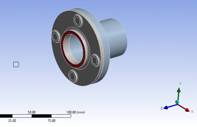
It is a 2-part flange assembly. The end of the pipe is fixed rigidly. There are four beam connections connecting the two parts together. The beams are scoped to the imprint of washers.

A frictionless contact has been defined between two parts. There is an external remote force of 1000N in the x direction, scoped to the surface in red (see below).

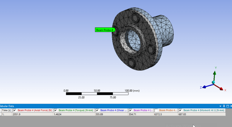
Large Deformation is on, and the beam probe data is shown below.

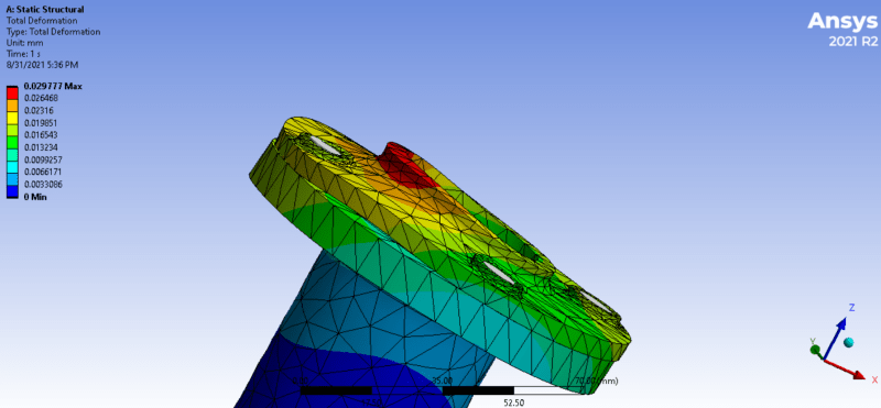
as you can see, the bending moments at I and J are quite different (6372 and 687). If I use the higher moment value(6372) and calculate the bending stress for an M10 bolt, the bending stress will be 649MPa. Is that number reliable? That means yield of my A4-80 bolts. Such a high moment could be interpreted given the image shown below: Due to the debonding, the force is applied through only a portion of the original scoped area, causing a large moment at the end of the beam.

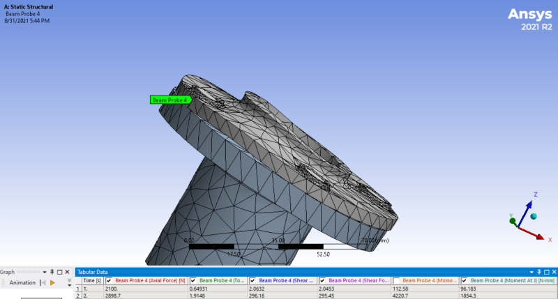
then, I added a pretension of 2100N and ran the simulation. the bending moments are still large (4220 and 1854). By the way, when I add a pretension and run it, the reported values at J are for midlength of the beam. Hence, it makes sense that the moment values at end of the beam (I) is different from that of the middle (J).

Hi,
I have a question about how to use beam probe data to conduct connection failure analysis? I know how to get the normal and shear stresses due to the axial force and shear force. Also, I know how to obtain the shear stress due to the torque. However, the bending moment is a bit unclear to me. Please take a look at the model below.
It is a 2-part flange assembly. The end of the pipe is fixed rigidly. There are four beam connections connecting the two parts together. The beams are scoped to the imprint of washers.

A frictionless contact has been defined between two parts. There is an external remote force of 1000N in the x direction, scoped to the surface in red (see below).

Large Deformation is on, and the beam probe data is shown below.

as you can see, the bending moments at I and J are quite different (6372 and 687). If I use the higher moment value(6372) and calculate the bending stress for an M10 bolt, the bending stress will be 649MPa. Is that number reliable? That means yield of my A4-80 bolts. Such a high moment could be interpreted given the image shown below: Due to the debonding, the force is applied through only a portion of the original scoped area, causing a large moment at the end of the beam.

then, I added a pretension of 2100N and ran the simulation. the bending moments are still large (4220 and 1854). By the way, when I add a pretension and run it, the reported values at J are for midlength of the beam. Hence, it makes sense that the moment values at end of the beam (I) is different from that of the middle (J).

