Continue to Site

Eng-Tips is the largest engineering community on the Internet

Intelligent Work Forums for Engineering Professionals

  • Congratulations cowski on being selected by the Eng-Tips community for having the most helpful posts in the forums last week. Way to Go!

Connection Design of Equipment Hanger Support 1

Status
Not open for further replies.

oengineer

Structural
Apr 25, 2011
731
I am working on designing the connection of an equipment hanger support.

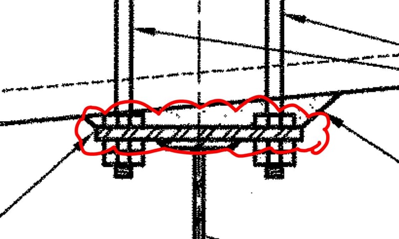
This link contains a picture of an example of the type of connection detail I am trying to analyze:

I am trying to determine the best way to go about analyzing this type of connection. This hanger connection detail is located in a roof (the precast concrete hollow core slab is in the roof) of a one story building.

I have no issues with the design of the S8x23 beam. The beam simple-span (from hanger connection to hanger connection) is 4'-0".

I am seeking suggestions on the connecting of the beam to the precast concrete hollow core slab. The 8 1/2" x 8 1/2" x 1/2" bottom plate shall be welded to the S8x23 beam, but what is the best way to verify the strength of the precast concrete hollow core slab holding up the hanger connect and beam weight?

Suggestions/comments are appreciated.

 
Replies continue below

Recommended for you

I have access to the PCI DESIGN HANDBOOK: PRECAST AND PRESTRESSED CONCRETE 7th Edition and do not see a connection design example that is similar to this situation. If anyone has access to this document and knows otherwise, please let me know.
 
Is this a new construction or an existing plank roof?

If new, I would show the detail and have the precast supplier design the plank for the required forces (that you indicate on your design drawings).

It may be that they will need to either verify the plank for the shear load - add additional tendons, etc.

If it is existing, you are essentially adding a series of point loads at 4 ft. spacings creating a sort of additional line load along the edge of the plank -
Assuming 100% of the line load is taken by the outer edge, I might see how the plank works by artificially up-scaling the line load for the whole plank...That might be too conservative - but otherwise you are depending on the line load to transfer across the top and bottom "flanges" of the plank to distribute it to the whole plank section.

 
JAE said:
Is this a new construction or an existing plank roof?

If new, I would show the detail and have the precast supplier design the plank for the required forces (that you indicate on your design drawings).

It may be that they will need to either verify the plank for the shear load - add additional tendons, etc.

This is NEW construction.

So, it is the precast supplier who would verify that the roof has the capacity to withstand the applied loads from the equipment hanger?
 
retired13 said:
The hollow core slab doe not hold up the beam, rather it is sitting on the beam, and is held stable by the clamp type connection. Since the slab is placed on a mild slop, you have to ensure the clamping force is adequate to resist the sliding force through shear friction.

The hanger detail shown in the link is attached to the ceiling/roof slab of the one-story building. So the hanger beam is suspended from the ceiling/roof slab.
 
The precast concrete hollow core slab is 8" thick.
 
I do some work for a hollow core manufacturer.

1) You can definitely hand of the design to the precast manufacturer but you'd be well advise to start them off with:

a) a good proposed detail and;

b) the reasonable expectation that the loading will work.

2) Whichever detail you use, I would advise not notching into the top of the plank for two reasons:

a) it's a giant pain in the butt to make those notches and;

b) the notches compromise the natural mechanism of the top flange arching between plank webs to competently distribute the load.

3) You can find a lot of the preliminary design information that you seek in Spancretes span note series which you can access here: Link.

4) When my particular precaster does this, we put embed plates in the bottoms of the plank, in the middle of the planks, and weld HSS hangers or something of the like to support the beam. It isn't the funnest thing to place an embed mid-span in the bottom of a plank but, for wet cast extrusions, it's not a big deal. Additionally, it's quite common for the roofing to be in place before the beam gets installed. The weld plates tend to make for easy support point coordination in this regard. While I like the weld plate solution for minor, hoist applications, I do prefer a through-plank connection solution for heavier loads where there is potential for fatigue/prying issues on the connection.

 
I read the wrong way, my comment was deleted. I agree that you need to talk to the hollow core supplier for recommendations.
 
You may need to investigate shear strength of the panels. This paper might help. Link
 
KootK said:
I do some work for a hollow core manufacturer.

1) You can definitely hand of the design to the precast manufacturer but you'd be well advise to start them off with:

a) a good proposed detail and;

b) the reasonable expectation that the loading will work.

2) Whichever detail you use, I would advise not notching into the top of the plank for two reasons:

a) it's a giant pain in the butt to make those notches and;

b) the notches compromise the natural mechanism of the top flange arching between plank webs to competently distribute the load.

3) You can find a lot of the preliminary design information that you seek in Spancretes span note series which you can access here: Link.

4) When my particular precaster does this, we put embed plates in the bottoms of the plank, in the middle of the planks, and weld HSS hangers or something of the like to support the beam. It isn't the funnest thing to place an embed mid-span in the bottom of a plank but, for wet cast extrusions, it's not a big deal. Additionally, it's quite common for the roofing to be in place before the beam gets installed. The weld plates tend to make for easy support point coordination in this regard. While I like the weld plate solution for minor, hoist applications, I do prefer a through-plank connection solution for heavier loads where there is potential for fatigue/prying issues on the connection.

So I went to the Link for the Spancretes website and found the material shown in the images below regarding concentrated loads on decks:

Concentrated_loads-untopped_deck_gapdnb.jpg


Concentrated_loads-topped_deck_gs3zv2.jpg


Based on the detail provide in my 1st post in this thread, it appears that the roof slab for this project is untopped.

The applied support reaction I have for my beam hoist & trolley system is 2.3 kips. Based on the images I have shown above, it appears that an 8" thick roof slab can handle the applied support reactions.

If someone has a different interpretation, please feel free to comment.
 
A couple of comments:

If this is an insulated roof, the little bit of bolt head which will be above the plank will easily be covered up by a couple inches of insulation. I wouldn’t worry about keeping the connection buried in the plank.

I’m not sure you will find an A325 bolt that long, or that you even want an A325 bolt at all. It’s not a good candidate for pretensioning even if you find the right stud to spec.

The point loads are pretty small, but be sure to combine them with your roof loads.

I know it puts the bolts close together, but I like to run the bolts right through the beam top flange where possible. The fewer welds involved in fatigue type situations the better. Local flange bending needs to be checked, of course.
 
JLNJ said:
A couple of comments:

If this is an insulated roof, the little bit of bolt head which will be above the plank will easily be covered up by a couple inches of insulation. I wouldn’t worry about keeping the connection buried in the plank.

I’m not sure you will find an A325 bolt that long, or that you even want an A325 bolt at all. It’s not a good candidate for pretensioning even if you find the right stud to spec.

The point loads are pretty small, but be sure to combine them with your roof loads.

I know it puts the bolts close together, but I like to run the bolts right through the beam top flange where possible. The fewer welds involved in fatigue type situations the better. Local flange bending needs to be checked, of course.

My next question was actually about how to check prying action for welded connections. This is due to how the beam is attached in the "section 'A'" view. See image below for the plate in question (clouded in RED):

welded_prying_action_hik3n7.jpg

(please see PDF in the 1st post for more info)


If I use a S8x23 beam and get rid of the 8 1/2" x 8 1/2" x 1/2" bottom plate, the workable gage for the S8x23 is only 2 1/4". Wouldn't this be very tight to have the bolts placed and extended into the roof slab?

If I go with the 8 1/2" x 8 1/2" x 1/2" bottom plate, is there any design information on how to verify the plate thickness for prying action for welding?
 
Are you asking how to analyze prying between the beam and plate for the weld at the edge of the flanges? If so, how do you envision prying forces developing in that scenario?
 
Rabbit12 said:
Are you asking how to analyze prying between the beam and plate for the weld at the edge of the flanges? If so, how do you envision prying forces developing in that scenario?

I may have phrased my question incorrectly.

I will be checking the thickness of the flange for the S8x23 beam for prying action. So, I am really asking about prying action for the S8x23 beam flange thickness, but it will be for a welded connection instead of a bolted connection.

I am not sure, Rabbit12, if you are hinting that if I am welding the ends of the beam flange end/edges to the bottom plate there should be no prying action affects (as long as the welds along the flange ends/edges are continuous through the plate).

I would imagine that I still need to verify that the thickness of the top flange for the S8x23 beam is adequate for my loading condition.

In regards to the 8 1/2" x 8 1/2" x 1/2" bottom plate, I am looking for any technical connection design info to verify that a 1/2" thick plate is adequate for this situation (i.e. trying to find the limit states to be checked for the plate for my situation).
 
You're correct I was hinting you won't have prying action developing on that type of connection. I suggest you review the prying action section in the AISC manual. The first sentence says it's a phenomenon for bolted construction only.

As far as flange bending it's a pretty simple calculation to find the stress in that flange. You can find the moment treating the flange as a simple beam with a point load at the center (web). Then it's just M/S where S is 1/6*b*t^2.

Same calculation method can be used for your plate.
 
Rabbit12 is right on the point.

Don't forget impact and effect of fatigue on the bolts and welds. Also, in addition to gravity load, the welds will suffer from shears produced by longitudinal/lateral thrust.
 
Status
Not open for further replies.

Part and Inventory Search

Sponsor