Continue to Site

Eng-Tips is the largest engineering community on the Internet

Intelligent Work Forums for Engineering Professionals

  • Congratulations IDS on being selected by the Eng-Tips community for having the most helpful posts in the forums last week. Way to Go!

Connection Detail for Cantilever

Status
Not open for further replies.

Szhc100

Structural
Jul 30, 2020
7
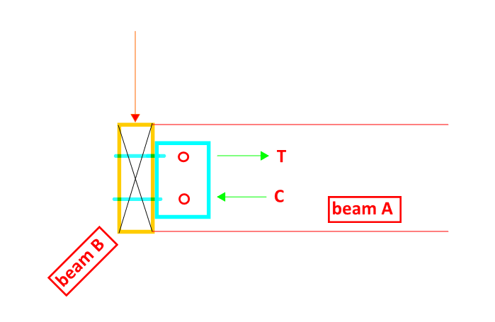
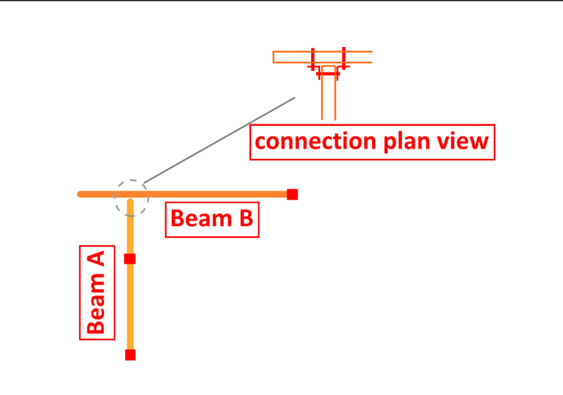
Hi, What would you suggest for connection between a cantilever timber/steel beam and another cantilever timber/steel beam shown as below? (Beam A supporting Beam B)
Due to the limitation of ceiling I cannot run beam A under beam B so I was thinking about using EA with 2-M16 bolts but I feel like I might miss something? Design V* = 45kN from beam B at connection.
22224444_cjdhgx.png
 
Replies continue below

Recommended for you

For timber to timber connection I'm more partial to an upside down facemount hanger where the bearing shoe goes on the supporting beam, and the supported beam gets the flanges against it. But this assumes the top of the beam is restrained from moving laterally.

For steel to steel, it depends on the shape employed. For wide flange to wide flange (or UB to UB if you're from overseas) I feel they'd likely just cope the flanges off the supporting beam and do a standard shear connection.
 
jayrod12 said:
For steel to steel, it depends on the shape employed. For wide flange to wide flange (or UB to UB if you're from overseas) I feel they'd likely just cope the flanges off the supporting beam and do a standard shear connection.
The problem with this sort of connection (if I'm understanding things correctly) is the lack of rotational constraint on beam B about its longitudinal axis. For this reason I normally go with a end-plate to web connection to provide twist restraint to beam B. Often beam B works well as a channel for this reason but obviously it depends on material and your requirements.
 

Supporting beam will be steel pfc while supported beam will be timber.

You mean cleat plate welded to supported beam B and bolts to supporting beam A right? The concern I have here is we are relying on the bolts to transfer the shear to supporting beam instead of applying the shear at the center line of supporting beam, which will cause twist like human909 mentioned.
 
Sorry but I cannot picture what you mean by end plate here? Can you please maybe provide a detail or elaborate on this? If a use Equal Angle like I mentioned, is it considered as sufficient twist restraint to beam B or it depends on the depth of EA?
 
Szhc100 said:
Sorry but I cannot picture what you mean by end plate here?
An end plate on the end of beam A going bolting through the web of beam B

Szhc100 said:
Can you please maybe provide a detail or elaborate on this? If a use Equal Angle like I mentioned, is it considered as sufficient twist restraint to beam B or it depends on the depth of EA?
The EA connection to B will have twist restraint but presumably its connection to beam A won't if it is bolted. Weld the EA to beam A and you are all good. But by this point you might as well just be using an welded end plate.

To elaborate. With the plan being X-Y, you want the connection to be rigid in y-axis and flexible in the x-axis. Your bolted EA connection is flexible along both axes.
 

Thanks for your explanation.
Can we use the bolts in beam A to form C/T couple to resist the twist as shown below?
4556_qwao8r.png
 
With normal hole tolerances you would get plenty of rotation. Unless of course you specified the bolts as slip critical and ensured they were designed and built as such. But that approach is normally more onerous.
 
Okay that makes sense. What if beam A is timber as well? what connection can be used to resist twist?
 
If both beams are timber, or even in the current situation, what is going on top of the beams? If there is some form of diaphragm, plywood or metal deck, then I would be counting on that for the lateral and rotational stability of the supported beam.
 
Status
Not open for further replies.

Part and Inventory Search

Sponsor