Eng-Tips is the largest engineering community on the Internet

Intelligent Work Forums for Engineering Professionals

  • Congratulations waross on being selected by the Eng-Tips community for having the most helpful posts in the forums last week. Way to Go!

connection steel beam - eccentric diagonal

Status
Not open for further replies.

Mike1998

Structural
Oct 5, 2018
9
NL
Hello everyone,

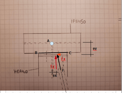
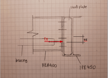
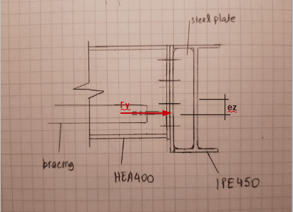
I am trying to check a connection between a HEA400 and a IPE450 and I have the following question, see also the attached sketch.

The diagonal of the horizontal wind bracing is connected eccentrically to the HEA400. The force in the diagonal gives two components. One parallel to the HEA400 and one parallel to the IPE450. The component parallel to the HEA400 gives a bending moment M=F*e which should be taken by the HEA400 and the connection. The component parallel to the IPE450, normally gives a torsion for the HEA400. Is this torsion transmitted as bending moment to the IPE450? Should I check both HEA400 (with that torsion) and the IPE450 (with the bending moment)?

Thank you in advance for your response.
 
 https://files.engineering.com/getfile.aspx?folder=c072b3e4-ed83-4de4-a1ec-316db5080547&file=connection.pdf
Replies continue below

Recommended for you

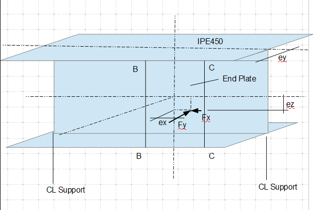
Hope these sketch helps.

image_dxqoj7.png

image_pwxcas.png
 
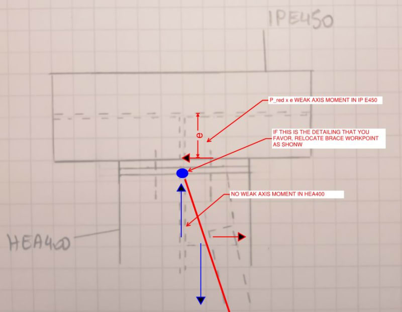
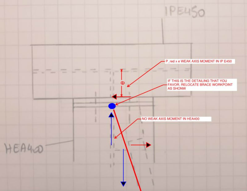
If this is the detailing that you favor, I would relocate the workpoint an use the statics model shown below.

In reality, I'd expect any moment in the joint to be shared by both members as weak axis bending in accordance with stiffness.

C01_d0n9xd.jpg
 
OP said:
The component parallel to the IPE450, normally gives a torsion for the HEA400. Is this torsion transmitted as bending moment to the IPE450? Should I check both HEA400 (with that torsion) and the IPE450 (with the bending moment)?

I get what you're saying and you're not wrong. I believe that the normal practice would be to ignore the torsion in the HEA400 and instead resolve the eccentricity via strong axis bending in the IPE450. In reality, you'll see some of both in proportion to the stiffness of each load path. That said, it is often the case that wide flange torsion is a flexible load path relative to strong axis flexure.
 
Those inner fillet welds can be tricky...[bigsmile]

Rather than think climate change and the corona virus as science, think of it as the wrath of God. Feel any better?

-Dik
 
Thank you all for your answers.

@Kootk

I agree with you. The plates are much stiffer than the web of the HEA and therefore the P_red will appear at the workpoint you show in your sketch. This will give a moment in the weak axis of IPE. And the other component a bending moment in the strong axis of HEA.

C01_d0n9xd_q080xs.jpg


But if I am not mistaken, even if ez is zero, I will always get the eccentricity you show in your sketch and therefore the bending moment P_red x e in the weak axis of IPE450, right? In order to avoid this moment I need another detailing, correct?

image_pwxcas_ty8dw7.png
 
I would 1) find reactions on the end plate points B and C - normal forces due to Fy, Fy*ex, Fy*ez, and shear force due to Fx; from here 2) treat these reactions as applied load to IPE450, and find reactions on the beam end supports.

image_jt1oyy.png
 
OP said:
But if I am not mistaken, even if ez is zero, I will always get the eccentricity you show in your sketch and therefore the bending moment P_red x e in the weak axis of IPE450, right? In order to avoid this moment I need another detailing, correct?

Yes, that is exactly right. This article may be of interest to you: Link. It contains the detail suggested below which you may find attractive if you wish to further reduce the weak axis bending moments.

C01_yecma7.jpg


c02_lom4wj.jpg
 
Status
Not open for further replies.

Part and Inventory Search

Sponsor

Back
Top