j_gautreau
Mechanical
Hello,
I'm a beginner in Femap and I have difficulties in connectors.
I've already read the article in the following link explaining different thing about contacts and try to applied all things but I think there is a problem again.
Link
The pin (in green) have a contact without space with the red sheet metal (INIPENE = 3) and have a contact with space with the blue sheet metal (INIPENE = 2). All sheet metal are linked with a bolt.
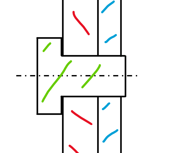
The model undeformed is the following picture
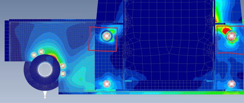
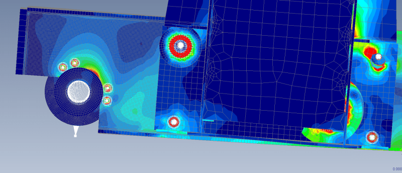
My problem is that the pin cross other sheet metal and some of the pin deformation are bigger than the real size, as you can see in the picture below.
I thank you in advance for your help.
I'm a beginner in Femap and I have difficulties in connectors.
I've already read the article in the following link explaining different thing about contacts and try to applied all things but I think there is a problem again.
Link
The pin (in green) have a contact without space with the red sheet metal (INIPENE = 3) and have a contact with space with the blue sheet metal (INIPENE = 2). All sheet metal are linked with a bolt.
The model undeformed is the following picture
My problem is that the pin cross other sheet metal and some of the pin deformation are bigger than the real size, as you can see in the picture below.
I thank you in advance for your help.