Eng-Tips is the largest engineering community on the Internet

Intelligent Work Forums for Engineering Professionals

Connectors, restrictions, loads - 60" steam pipe ASME BPVC analysis

Status
Not open for further replies.

vtpsantos

Mechanical
Apr 12, 2023
7
0
0
BR
Guys,

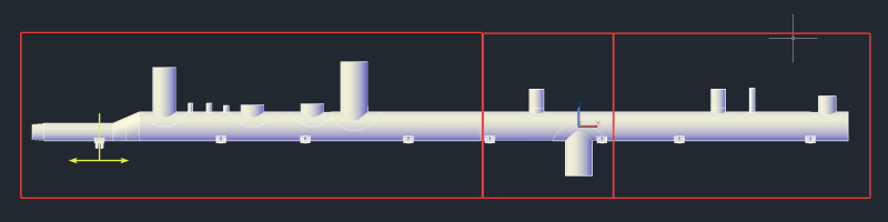
I'm evaluating a 60" steam pipe according to ASME Section VIII Div. 2 using Inventor Nastran. There are some branches from 8" to 56" as you can see below; these branches continue as secondary pipes. This pipeline will operate between 170~400ºC (445~675K). I also separated FEA models in three groups(represented by red squares) to simplify load inputs, match with my beam element piping stress analysis software (TRIFLEX) and otimize mesh generation and computational resources.

acad_2wa2FoShST_ej4bmr.png


Taking the mid-piece as example, I created four central points in order to use with Connectors and input displacements/loads given by TRIFLEX analysis.

mspaint_sbcQVwVthl_l3hdun.png


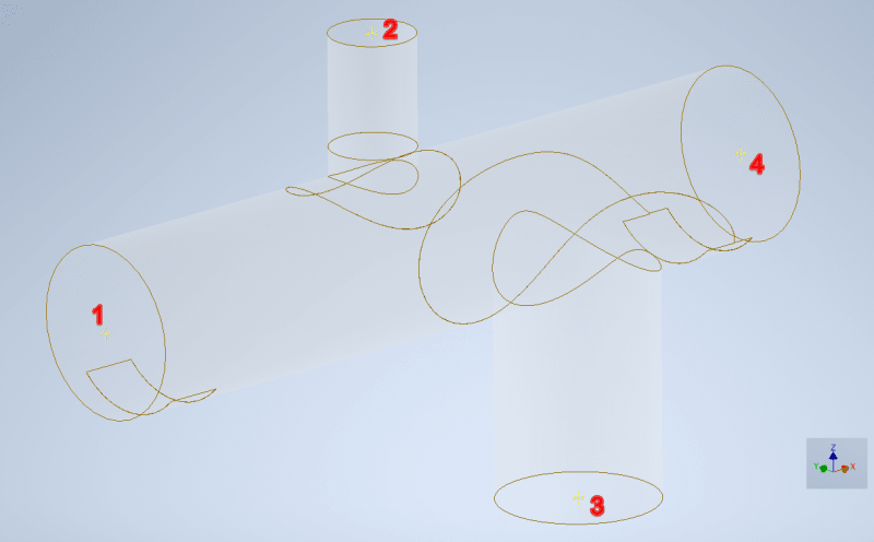
The most logical way to input these loads, for me, is by applying displacements at points 1/4 associated with Rigid Connector Elements (RBE2) and forces/moments at points 2/3 associated with 'Interpolation' Connector Elements (RBE3). These connectors link central points to correspondent circular edges. But at this point doubts begin:

1 - Every time I consider body temperature and displacements at both 1/4 points, it seems like if the model expands more/less than the difference between displacements of points 1/4. Should there be any difference between beam/3D models expansion between these points? Is usual to consider back extremity (point 4) without any constraints?

2 - Is really necessary to input displacements? I ask because the entire body will expand independently of which displacement is inputted at point 1. It makes sense if studying the effect of friction on stresses around pipe support, for example, but thinking about branches it seems like something that will just complicate my analysis. Forces/moments given by TRIFLEX already consider thermal effects (but separate it between thermal and weight+pressure still possible).

3 - Connectors' DOF. If I consider all translation DOF constrained, relative body expansion on radial directions due to internal pressure and thermal effects are impossible. But allowing these movements, usually calculation returns fatal error due to excessive lack of constraints. I know there is not a 'standard recipe' to do this, but I really don't find trusted content and opinions about, especially talking about Inventor.

Maybe this problem is a little different from usual vessel analysis, but I think that anyone who knows the minimum about how to input loads in nozzles could give me a good orientation.

I would like to say that I'm a beginner with FEA and my knowledge with Inventor Nastran / ASME VIII is limited, so all your opinions and help are always very welcome.

Thanks in advance

Vinício.
 
Replies continue below

Recommended for you

You definitely want to be applying forces and moments instead of displacements. At worst, you likely need to anchor (fix) one location (I recommend #1 or #4) to avoid free body motion and apply forces and moments everywhere else. Apply these forces and moments using RBE3s.

Coming back, though, to focus on the VIII-2 Part 5 evaluations - I have the following questions for you:
1) For demonstrating Protection Against Plastic Collapse - which analysis method are you going to use: Elastic, Limit Load, or Elastic-Plastic?
2) For demonstrating Protection Against Local Failure - which analysis method are you going to use: Elastic or Elastic-Plastic?
3) For demonstrating Protection Against Collapse from Buckling - which analysis method are you going to use: Method A or Method B? Please, please, please, use the 2023 Edition for this failure mode and not any earlier editions.
4) For demonstrating Protection Against Failure from Cyclic Loading: Ratcheting - which analysis method are you going to use: Elastic or Elastic-Plastic?
5) For demonstrating Protection Against Failure from Cyclic Loading: Fatigue - which analysis method are you going to use: Elastic or Elastic-Plastic?
6) Further to question 5 - how are you going to handle the fatigue at your welds: the FSRF method or the Structural Stress method?
 
TGS4, I'm glad about your answer. Fixing extremity #1 and keeping #4 guided seems like the most "natural" way to consider taking in account structure behavior. About displacements and loads associated with connectors, could you help me with which DOF's I should consider in the dependent edge? Per VIII-2, is there a minimum distance to take in account from the extremity to the analysis region of interest? I saw 5*sqrt(r*t) in other topic, but I'm in doubt if this value is given by VIII or just a [good] FEA recommendation.

About your questions:

1) For demonstrating Protection Against Plastic Collapse I'm going to use Elastic method as a primary/conservative solution and Limit Load method as a 'double-check'. I think avoid inputting displacements may help with calculation convergence in Limit Load due to Large Displacement parameter setted "Off", right?!
2) For demonstrating Protection Against Local Failure I'm going to use Elastic method, but Inventor has limitations with stress caracterization to obtain the sum of primary principal stresses, so it will need a submodeling of peak stress regions using solid elements. Could Elastic-Plastic method give me better results or minimize this submodeling/pre-processing time?
3) For demonstrating Protection Against Collapse from Buckling, well...I'm obtaining eigenvalues from linear buckling analysis in total vacuum condition with associated nozzle loads and comparing these values with design factors given by 5.4.1.3. Sorry, for "Method A/B" would you like to say "Types" from 5.4.1.2? Now I'm worried about rule edition, VIII 2019 is the last edition that I have. Are there so much differences in buckling analysis methods?
4/5/6) So far I'm not considering Cyclic Operation. This system will operate in long period cycles. Should I consider this mode of analysis?

One more time, sorry about my shallow knowledge about VIII and thank you for your help.
 
Happy to help. I wouldn't worry too much about the minimum distance to the load application points - that's more a good FEA practice aspect than a Code requirement.

1. Sounds good. If you use Limit Load, applying displacements may artificially prevent collapse and give you the impression that things are OK when they are actually not. So I would not recommend applying displacements as boundary conditions.
2. Elastic is likely the best way for you. In fact, I would seriously investigate the exemption provided in 5.3.1 - given your geometry.
3. I certainly meant Method A/B from the 2023 Edition. The 2023 Edition is a complete rewrite of the buckling rules - mostly because the prior editions' rules were potentially unconservative - especially the Type 1 analysis. Please, please, please use the 2023 Edition buckling rules!
4. Ratcheting check is mandatory.
5/6. You may be exempt from fatigue analysis, but go through the fatigue exemptions first.
 
vtpsantos said:
I think avoid inputting displacements may help with calculation convergence in Limit Load due to Large Displacement parameter setted "Off", right?!
What do you mean by this? Prescribing either load or displacement should be fine if the solver has an arc-length implementation. Displacement control can handle snap-through (not snap-back, though), while load control cannot. Limit load analysis by non-linear static analysis may become troublesome with load control without an arc-length method.

vtpsantos said:
2) For demonstrating Protection Against Local Failure I'm going to use Elastic method, but Inventor has limitations with stress caracterization to obtain the sum of primary principal stresses, so it will need a submodeling of peak stress regions using solid elements.
What do you mean by "sum of primary principal stresses"? If you are doing design based on analysis, the von Mises stress would be of interest in the elastic analysis.

vtpsantos said:
3 - Connectors' DOF. If I consider all translation DOF constrained, relative body expansion on radial directions due to internal pressure and thermal effects are impossible. But allowing these movements, usually calculation returns fatal error due to excessive lack of constraints. I know there is not a 'standard recipe' to do this, but I really don't find trusted content and opinions about, especially talking about Inventor.
The calculation will indeed fail if the global stiffness matrix is singular. Furthermore, prescribing boundary conditions is not specific to your software, and details can surely be found in the literature of pressure vessel design. My suggestion is to apply the restraints you would expect in real life, with some exemptions, such as avoiding BC:s causing non-linearity (e.g., compression-only supports and the like) and avoiding over-constraining the model (think of a simply supported 2D beam in which one end is allowed to translate in the axial direction to prevent the beam stiffening due to geometric non-linearity).

What is the size of this pipe? If the dimensions are e.g., 0.5 meter diameter and 10 meter non-curved segments, you could probably use beam elements.


TGS4 said:
4. Ratcheting check is mandatory.
5/6. You may be exempt from fatigue analysis, but go through the fatigue exemptions first.
Sorry, I'm already checking ΔS[sub]n,k[/sub] ≤ S[sub]PS[/sub] according to 5.5.6.1. I'm just in doubt about what is the "combination of cycles", described at (c). I'm running linear elastic subcases with different temperatures (from 170 to 400ºC) and comparing Von Mises Stress to S[sub]PS[/sub] limits considering the average of S values at highest and lowest temperatures. Is that correct? Should I run non-linear to perform correct cycles stress evaluation? About fatigue exemptions, I'll check it better to be sure.

centondollar said:
What do you mean by this? Prescribing either load or displacement should be fine if the solver has an arc-length implementation. Displacement control can handle snap-through (not snap-back, though), while load control cannot. Limit load analysis by non-linear static analysis may become troublesome with load control without an arc-length method
So, arc-lenght method is built-in solver, isn't it? I'm using Nastran. I mean I think inputting displacements in this case will just turn analysis worst to converge because of Small Displacement theory, and, if arc-lenght method prevent it, sorry for my amateurism.

centondollar said:
What do you mean by "sum of primary principal stresses"? If you are doing design based on analysis, the von Mises stress would be of interest in the elastic analysis.
To prevent local failure, according to 5.3.2, triaxial stress limit should be checked by (σ1+σ2+σ3) ≤ 4S criterion, but Inventor doesn't have an easy way to do it using Contourns associated with shell elements.

centondollar said:
My suggestion is to apply the restraints you would expect in real life, with some exemptions, such as avoiding BC:s causing non-linearity (e.g., compression-only supports and the like) and avoiding over-constraining the model (think of a simply supported 2D beam in which one end is allowed to translate in the axial direction to prevent the beam stiffening due to geometric non-linearity).
Actually my complete loads and constraints settings is:

Extremity #1: Central point full constrained associated with RBE2 connector on which dependent elements have rotational DOF's and X translational (pipe/vessel axis) DOF constrained.
Extremity #4: Central point constrained only in Y axis (radial horizontal direction) associated with RBE connector on which dependent elements have only rotational DOF's constrained.

Nozzles #2 and #3: Central point with loads (forces and moments) associated with RBE3 connector on which dependent elements are full constrained.

Pipe support near to #1: TY, TZ, RX, RY constrained.
Pipe support near to #4: TZ, RX, RY constrained.

Taking into account that I'm inputting only loads (and not displacements) it seems to be the most natural way to constrain the model, except TY on support near to #1, but it was necessary to prevent excessive Y-axis structure displacement.

centondollar said:
What is the size of this pipe? If the dimensions are e.g., 0.5 meter diameter and 10 meter non-curved segments, you could probably use beam elements.
Main pipe diameter is 60" (~1.5 meter), and total length is over 35 meters.


Don't get into arc-length methods or similar for ASME Code analyses. We are actually trying to find non-convergence...

When it comes to FEA for the ASME BPV Code, I highly recommend that you ignore those folks that don't know or understand the Code. They are very likely well-meaning, and may be very knowledgeable about general FEA methods, but the rules in ASME Section VIII, Division 2, Part 5 are very specialized.
 
TGS4 said:
Don't get into arc-length methods or similar for ASME Code analyses. We are actually trying to find non-convergence...
Non-convergence doesn't guarantee that you've found the collapse load if the solver is unable to traverse local maxima. The physics is what one wishes to capture by modelling, and so an analysis with an insufficient numerical scheme leading to artificial results is of no use.

vtpsantos said:
So, arc-lenght method is built-in solver, isn't it? I'm using Nastran. I mean I think inputting displacements in this case will just turn analysis worst to converge because of Small Displacement theory, and, if arc-lenght method prevent it, sorry for my amateurism.
I am not familiar with Nastran. Regarding displacement control, its possible usefulness is not related to small displacement theory, but rather in the ability to traverse snap-through behaviour common for metal shell collapse.
 
centondollar - whether one finds a "local maxima" or a global maxima, the ASME Code is clear that it is requesting that it be "demonstrated that equilibrium be satisfied in the undeformed configuration" to satisfy Protection Against Plastic Collapse using the Limit Load Analysis Method. In my experience, those who use a Rik's Method or Arc-Length method when trying to satisfy this requirement often are misunderstanding the ASME Code fundamentals and are trying to apply a purely FEA-based approach - typically to their detriment.

Further, the Code is very intolerant of any local "buckling" behaviour, especially snap-through buckling. Such behaviour can lead to very low-cycle fatigue or even crack initiation in the first cycle - cracks which a corrosive environment can take advantage of and create huge problems. Never a good idea when trying to contain pressure.
 
vtp - what solution type are you using in Nastran? Presumably linear elastic? (I don’t know what capability “Inventor Nastran” has, but it sounds like some sort of dumbed down auto thingy for designers).

And why do you need to use a FEM to analyze a steam pipe??? Thousands of miles of steam pipe have been designed without a FEM.
 
If you want to analyze a pressure vessel against plastic collapse, then you need to run a non-linear static analysis with a solver that can trace the complete equilibrium path. This can be one with moderate rotations (geometric non-linearity) and infinitesimal strains, satisfying the criteria "equilibrium in the undeformed configuration".

Linear analysis with dimensions chosen so that no part yields is a different story entirely. Is the "Limit Analysis Method" based on evaluating linear elastic stresses? This was not clear to me, since you talk about "plastic collapse" in the same sentence.
 
centondollar said:
vtp - what solution type are you using in Nastran? Presumably linear elastic? (I don’t know what capability “Inventor Nastran” has, but it sounds like some sort of dumbed down auto thingy for designers).

As info: "Inventor Nastran" is based on NEiNastran. I used NEiNastran until Autodesk bought the rights to the solver. That was a very capable solver but I don't know how much of the capabilities that are accessable trought Inventor today.


From what I can see in the first post there are details that might motivate FEM. But it seems unnecessary to analyze the entire pipe in FEM. For a beginner in FEA I would not recommend that approach [smile].
 
SWComposites said:
what solution type are you using in Nastran? Presumably linear elastic?
For demonstrating protection against plastic collapse, local failure and ratcheting I'm using Inventor's Linear Static solution. For Limit Load method, Nonlinear Static. And for buckling, Linear Buckling.

SWComposites said:
And why do you need to use a FEM to analyze a steam pipe??? Thousands of miles of steam pipe have been designed without a FEM.
Because according to ASME B31.1/B31.3, branches of pipelines that have D/t (diameter/thickness) ratio over 100 need to be evaluated using FEA. ASME provides SIF's (Stress Intensification Factors) for piping stress calculations in which D/t < 100. My pipeline has a diameter of 76" and thickness of 3/8" (D/t = 202,56). Of course, there are alternatives to obtain calculated 'out-of-code' SIF's, but I do not have any software capable to do it. In addition, if someone know how to get these pipe SIF's using Inventor Nastran, please teach me.

ThomasH said:
But it seems unnecessary to analyze the entire pipe in FEM.
Even taking into account the premises of the rule I mentioned above? Since I understood that displacement are not so necessary to evaluate this model, I think about analyze branches one-by-one into individual models. Is that you're trying to say? Or do you have another recommended approach?
 
When you say you are using "Nonlinear Static", what nonlinerarities have you included? Material and large deflection comes to mind. Anything else?

Regarding the SIF's, what are those stress intensification factors based on? What is the cause for the stress intensification?

vtpsantos said:
Even taking into account the premises of the rule I mentioned above? Since I understood that displacement are not so necessary to evaluate this model, I think about analyze branches one-by-one into individual models. Is that you're trying to say? Or do you have another recommended approach?
The problem I can see relates to the SIF's. What is it that ASME requires from FEM when it relates to slender structures? I suspect a non linear solution but how should that solution be set up?
 
I don't need a training course to understand what e.g., plastic collapse or non-linear static analysis entail, but perhaps you do, since you were unable to answer my questions.
 
vtpsantos said:
For demonstrating protection against plastic collapse, local failure and ratcheting I'm using Inventor's Linear Static solution. For Limit Load method, Nonlinear Static. And for buckling, Linear Buckling.
It is not possible to predict local failure with a linear analysis. Perhaps you mean satisfaction of code-mandated limits on e.g., von Mises stresses?

What options are you using to predict the limit load? Are you using a scaled buckling mode - common practice in many fields - as initial imperfection for your pipes? Many things can go wrong when running non-linear analysis, particularly if the software one is using is unable to trace post-buckling behavior. I am not knowledgeable about the code you are using - does it really require all the analysis you are currently performing? If that is the case, you ought to use software that is guaranteed to solve the problem correctly - Ansys, Abaqus (and probably MSC.Nastran) come to mind.
 
centondollar said:
I don't need a training course to understand what e.g., plastic collapse or non-linear static analysis entail, but perhaps you do, since you were unable to answer my questions.
I teach the course on DBA for the pressure vessel Code. I am one of two instructors in the entire world on the topic. It is not my responsibility to teach you about the Pressure Vessel Code - that you need to take on yourself.
 
vtpsantos - since you are performing this analysis for the sole purpose of calculating the SIF, I highly recommend that you hold off on your (full-blown) analysis and focus on calculating the SIF. B31J has direction on how to do that.

I highly recommend that you continue this discussion in either the Pipelines, Piping, and Fluid Mechanics forum, or the ASME (Mechanical) Code Issues forum. Posting here in the General FEA forum will end up just distracting you from your actual problem.
 
centondollar said:
Ansys, Abaqus (and probably MSC.Nastran) come to mind.
Quite correct. Depending on the details in the analysis, MSC, NX and NEiNastran can all do this, I have done it in all of them. Today I would probably perfer Adina for several reasons.

I am not familiar with ASME but Eurocode has rules for elastic-plastic failure. That includes initial imperfections (based on scaled buckling mode(s)), non linear material and non linear geometric behaviour. But that type of analysis also often includes methods that for some reason it seems that ASME doesn't like, like line-search.

Is the problem in this thread related to FEA? Since we are in that forum I thought that was the question.

 
Status
Not open for further replies.
Back
Top