Continue to Site

Eng-Tips is the largest engineering community on the Internet

Intelligent Work Forums for Engineering Professionals

  • Congratulations waross on being selected by the Eng-Tips community for having the most helpful posts in the forums last week. Way to Go!

Construction Joint provided at location of Maximum shear and Moment's demand 2

Status
Not open for further replies.

M.IDR

Structural
Dec 31, 2020
42
A contractor has provided construction joint at the location in Raft construction where the shear and moment is maximum at that location. So, any one does have any solution how can it be verified, if this construction joint is feasible or it needs rehabilitation?

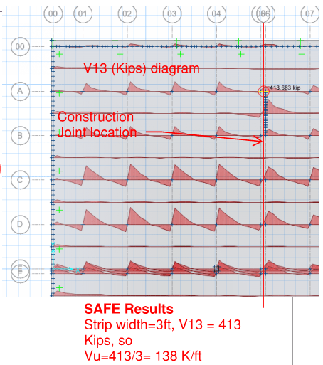
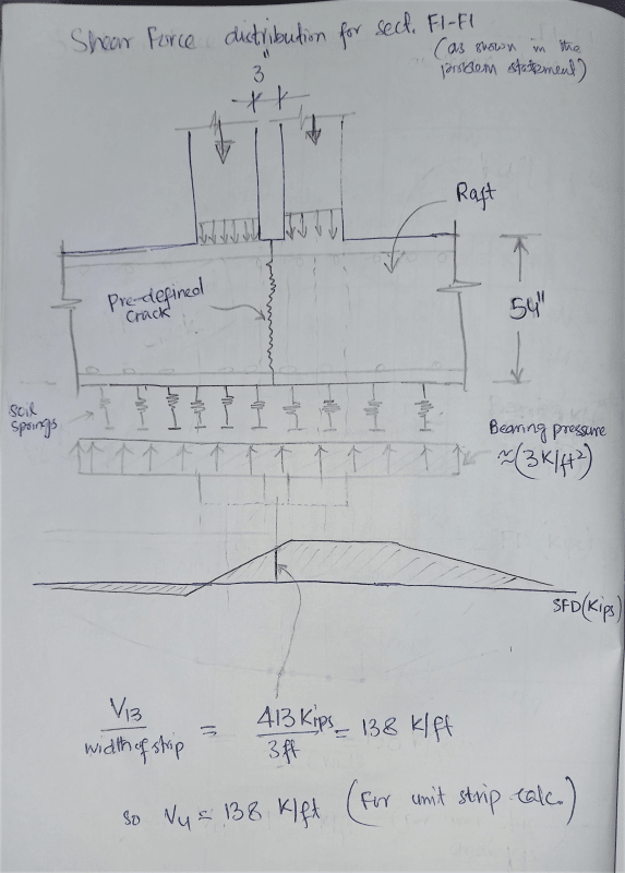
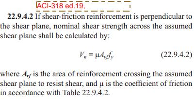
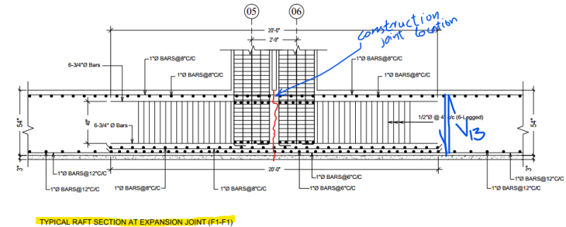
By considering shear friction design based on ACI-318-19 sect. 22.9, the bottom steel is not enough to resist the applied shear demand coming at the location of construction joint. The demand value of shear is shown in the figure below
image_putghn.png

image_bnsqf9.png

The design section detail is provided in the the section F1-F1
image_t6uum8.png

The Calculations are shown below, as the surface of the joint is not roughened intentionally rather it is smooth, so mu= 0.6,
By only considering the Bottom steel (in Tension), the shear friction capacity is not enough to resist the demand,
and i don't think that the top steel is contributing to shear friction.
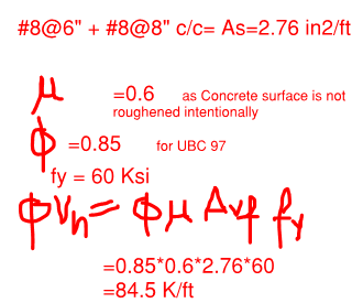
phi Vn < Vu not OK
image_k3qf2u.png
Malang_wazir
 
Replies continue below

Recommended for you

Is this a SOG? If this is the case, I would not worry too much, as the top of the beam is subjected to compression and closed tight.
 
@r13 yes it is Slab on Grade (SOG), Can you elaborate why?

For your information, these columns are heavily loaded, to reduce the punching shear in the raft integral beams are provided and if construction joint is provide between the columns at the expansion joint, so won't it be critical?

 
1) You can eliminate dead weight of the raft, it won't produce internal stresses, as it is rested on and balanced by subgrade.
2) You are quite conservative on shear friction calculation, by consider the bottom steel only.
3) We don't rely on the shear strength produced by compression on concrete above the neutral axis, but it does exist, though subject to scrutiny.
 
@r13 as if you review the research paper of ACI Journal by Mattock and Birkland, The Shear Friction capacity is produced because of the rough surface which causes tension in the steel after separation between the faces caused by the shear at the crack. However in ACI 318 it is not clearly mentioned to use the compression steel as well in shear friction. Moreover shear is applied on the steel won't it produce additional stress in the tension steel as it has already reached to its yield capacity due to flexure.

REFERENCES:
Shear Transfer in Reinforced Concrete-Recent Research Alan H. Mattock and Hawkins 1972
Connections in Precast Concrete Construction by Philip W. Birkeland and H. W. Birkeland 1966
Wazir_Malang

 
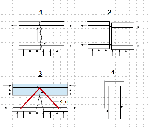
I think my previous responses are shady, as there is no theory, nor code provisions to back up those comments. I don't want to mislead you, but to offer my thoughts on this matter for you to judge. Sketch below demonstrates that. Figures 1 and 2 are self-explanatory, note that the reinforcement will be mobilized once the concrete blocks start to slip. Figure 4 is a baffle block on slab with dowels for shear friction, which is quite common on hydraulic structures. You really have to give a hard look on figure 3, ask how the slip is going to occur, what components can be utilized to resist the shear force, and to what extend. Unfortunately, there is no clear cut answer to each of those question. I won't spend any time to think about how to justify a construction mistake, if there are simple solutions available. I wish you luck.

image_gzmi0t.png
 

The CJ location provided by the contactor is not reasonable.. The expected location of CJ is at a distance L /4 ( L is the span)... However, your approach is also not reasonable..

Apparently the shear V= 413 kips at just under the column axis 6. The CJ provided between two columns and the shear which will be experienced by CJ should be less than 413 and would be around zero if the column loads are similar.
Moreover, say your figure is correct, what is the reason for checking shear friction for 1 ft width ? if d=54 in. you may check for a width 3d.

The one way shear is checked at a distance (d) from the column face and for two way shear at a distance d/2.

Does this respond answer to your question? If not, you may perform the mat analysis with more refined mesh and check the shear friction for a width say 3d .


HTURKAK said:
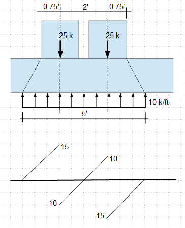
the shear which will be experienced by CJ should be less than 413 and would be around zero if the column loads are similar

Share the same thought here. For example,

image_xzimbd.png
 
Dear, @HTURKAK As I am not sure about how much width of strip should be considered for acting as a unit, so conservatively 3ft strip width is considered to act as a unit, if you have a proper reference for it's consideration, I would be glade to know.

@HTURKAK There is no concept of one way or two shear here, as in that case we have a monolithic RC section and our most possible failure in one way or two way @45deg, depends on distribution of loads.
But Here it is a predefined crack at which shearing off the two opposite concrete faces is very much possible to occur at that location.

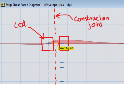
Dear, r13 and @HTURKAK The way you visualized the load distribution is quite good but more like for a rigid system and i don't think it clearly represent my problem, However the problem is that it is SOG(Slab on Grade) as in the figure below, the shear caused by these vertical loads will definitely make it zero but not in between the columns while it will be much away from the columns, as actual distribution of shear force is shown in the below figure and from the CSI SAFE Results
image_wspvws.png

image_kmpvle.png
 

The sectional strength of RC members are calculated as per ACI 318 22.5 ,( for 318-14, section 22.). You may use the analogy of flat slab. Remember the width for beam and column strips. In this case you may assume the width conservatively 0.25L.


I disagree with you ..you are expected to check one way and two way ( punching shear ). What is the difference of axes A-5,6 ? while at the other axis (5,6,7..) the shear is around zero?.. Check the input data specially column loads ..

Good luck..
 
I don't know what you can obtain from your program, and how does it checks internal stresses. I suggest to exclude the slab dead load in load combination, and get the axial force and moment on the joint. Then perform a hand calculation to find the compression force on the top face. You shall be permitted to utilize the shear friction, µF, in addition to shear friction capacity provided by the reinforcement. If the resulting capacity is close to within 10% of the demand, I would accept it.
 
@r13 There is no change in the shear force demand after the dead weight of the slab is assigned zero. By Considering the capacity of the compression force in concrete as additional force to the bottom steel causing friction as
Vn = µF + µAs(bot)fy

can fulfil the demand shear Vu.
But the confusion is that the bottom steel is already at yielding due to moment so can it take additional stresses due to the shear? if no then we are only left with the µF as causing the shear friction.

While, I am thinking why do we need to provide integral beams below columns, if the shear friction capacity is enough to resist the axial loads on columns?
 
1) On the dead load, no change is the expected result, but a double check since sometimes the program, or person, would make mistakes.
2) The use of shear friction is to be avoid for its uncertain natures. You will not find any literature that discuss shear friction for flexural members, but I explained before, on why we are looking into it.
3) The question on utilizing the bottom steel is a good one, to which the answer would be negative.

So the verdict is the beam requires rehabilitation/strengthening. But before jumping off the train, I suggest to relief the vertical restrain of the joint, if your program allows you to do so, to see the effect of this change. Note that the increase in bearing is anticipated, and it is acceptable if kept within a factor of 1.5.
 
@r13 for Strengthening epoxy will be used at the construction joint? do you have any suggestion which epoxy should be used?
 
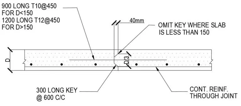
When a construction joint is required in a mat foundation, my preference is to locate it at centre span where shear is minimal. In addition, I specify provision of a key about 1/3 the thickness, and some big dowel bars in the middle of the key. Belt and braces approach, for sure, but a mat foundation is not to be trifled with.
 
Dear @hokie66, Thank you for your response. In case of construction won't it be good to provide key at L/3 (where minimum V and BM) with a key and not in the middle as there is max BM in middle?

You are suggesting to provide key of this type? is the key would be a little odd if extra dowel bars are not provided in the middle?
image_fpqlg9.png


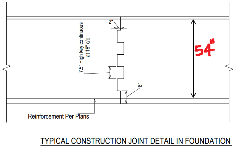
As the mat foundation thickness is 54" so won't the shear key shown in the figure below, more suitable, to have a more roughness and all that without a dowel bar in the middle?

image_glh9aw.png
 
I know some folks like the L/3 arrangement, but I would rather see it at midspan. Theoretically minimum shear, maximum moment. The moment is taken by the T-C couple, which is unaffected by the joint.

The sawtooth key can work, but is a lot of extra labor. I would just use a single key 18" deep, with some big deformed dowel bars central to the key.

Others will have different ideas, but that is the way I have detailed construction joints in mat foundations for many years.
 
@hokie66 noted with thanks.
 
One other thing. There was some mention of epoxy being used in the joint, presumably as a bonding agent. I wouldn't try to do that, as those materials are very time sensitive, and are more likely to act as a debonder.
 
Wazir,

Wasn't this mat has already done, with the second lift placed against an unprepared surface? Or it is still on the drawing board waiting to be constructed? I'm a little confused here. But as Hokie pointed out, the epoxy wouldn't do any good at this situation.
 
Status
Not open for further replies.

Part and Inventory Search

Sponsor