Continue to Site

Eng-Tips is the largest engineering community on the Internet

Intelligent Work Forums for Engineering Professionals

  • Congratulations IDS on being selected by the Eng-Tips community for having the most helpful posts in the forums last week. Way to Go!

contact errors 2

Status
Not open for further replies.

saja11

Bioengineer
Aug 2, 2019
42
Hi all
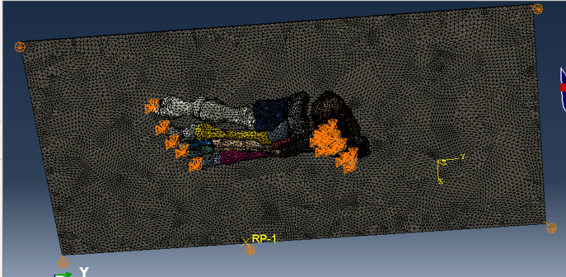
I am modelling neuropathic foot bones. I have segmented 19 bones via MIMICS software. For meshing I used MATIC and Hypermesh. Now I am trying to simulate the neutral standing position of foot with Abaqus/Implicit (Quasi Static).I considered bones to be elastic and giving material (Young's Modulus=7300, poisson's ratio=0.3, density=4.49e-10) to each bone.I fixed the upper surface of tibia and giving concentrated force of 350N from below the ground.

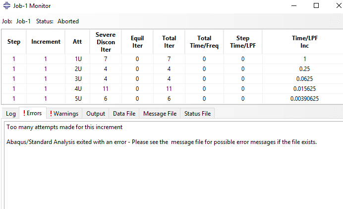
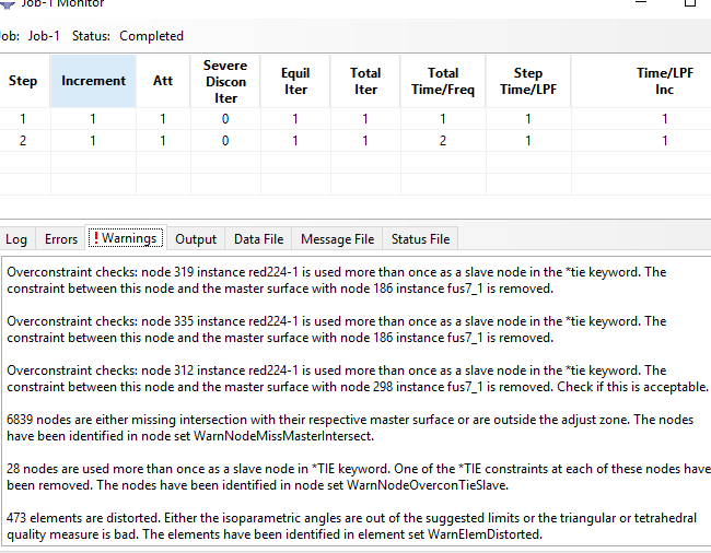
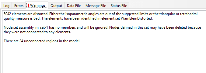
I want to have a surface to surface contact between bones (finite sliding, frictionless) and between foot and ground (hard contact,finite sliding,penalty 0.6) but due to convergence error job get aborted.I tried changing increment in step and through solver control but still getting increment errors.In warnings I am getting some unconnected regions but as its a neuropathic foot it have some bones eroded. I am stuck in this for several days and can't figure out problem in my project. Kindly can someone guide me what I am doing wrong.
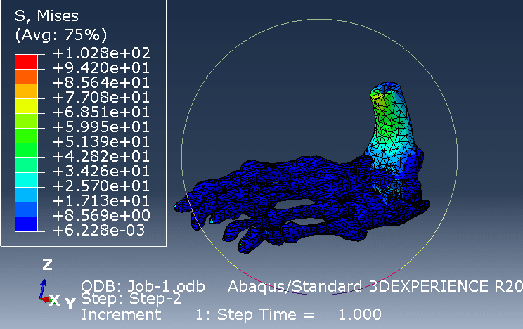
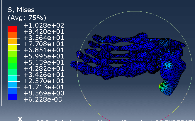
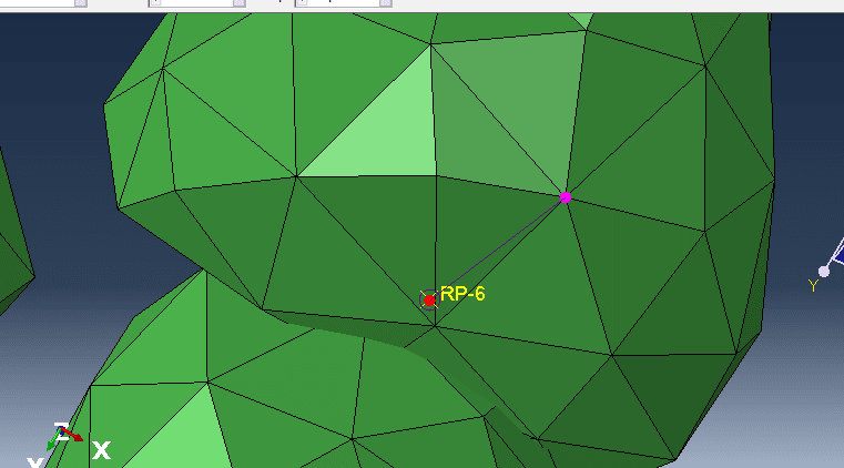
Below are some pics of model and warnings.
Capture_hsc006.png

foot_gnd_whvvls.png

job_monitor_pagtkf.png
 
Replies continue below

Recommended for you

Well the bones are loose and unconnected (See message 24 regions are unconnected) so you need to have some form of connection say tendons/muscles/tissue to keep them together, and then you can have contact to keep them together (or cartilage between them with contact to the bone).

See this paper on how to model this :

 
You can try this approach: tie all these bones together (if they are too far use coupling with common reference point or connector to join them), see if it solves (if not use modal analysis or datackeck with unconnected_regions=yes to see which bones are not properly connected) and then introduce contact pairs one by one (you can use Find contact pairs tool to change the type of contact faster). This way you will see which pairs are causing problems.
 
Thanks for your replies
I defined surface to surface interactions between bones again. Now 8 unconnected regions are left and job gets aborted due to same convergence errors.How can I view these regions?Attached are warnings coming now.
I tried to simulate same model by using tie constraint between bones and my job gets completed but pressure is not distributing properly and most of papers are using surf to surf interactions btw bones.
At this stage I want to simulate bony part of foot only hence not modelling cartilage yet.
 
 https://files.engineering.com/getfile.aspx?folder=4b6ddf80-c9a4-4492-b13d-ea90970ab9de&file=warnings.txt
To see these unconnected regions follow procedure mentioned in my previous post - run datacheck analysis from command line adding unconnected_regions=yes. Abaqus will create sets containing elements and nodes in these regions. However keep in mind that some of the reported unconnected regions are correct. For example when initially open contact is defined between the surfaces and it doesn't close during the simulation because the deformation is low enough to keep these surfaces away from each other. Modal analysis will also be very helpful to visualize unconnected components but all contacts must be switched to tie in this case. Zero pivot error indicates that some parts are not properly connected and they experience rigid body motions.

Can you attach a picture with results from the completed analysis ?
 
Check the set WarnNodeMissMasterIntersect. It will show you which regions are too far for interaction to join them with specific adjustmenr tolerance. You may have to increase this parameter but be careful - too high tolerance will force connections between nodes that shouldn't be joined and thus lead to severily distorted elements (even to the point that "zero or negative mass" error appears). You may have to connect some bones with couplings or connector elements if they are far from each other. And maybe general contact will work better. You can test it in Explicit since its formulation works best with this solver.
 
I'm having some tough luck to determine optimal tolerance value to merge the instances till now but I am trying to find a value which can merge my bones.
I tried general contact (all with itself) in dynamic explicit but gets error as "The analysis may need a large number of increments (more than 20,000,000), and it may be affected by round-off errors. For accuracy, running double precision executable is required."

I also tried connector between two bones only for now,creating two nodes on both bones from sets and used connector MPC-Pin between them...still convergence issue remains there.(Is this the right way to do it?)
I am confused all these errors are because of untidy mesh or due to my obvious blunders in Abaqus simulation setup.
And thanks for your kind help till now.Your help is very much appreciated.
 
When choosing tolerance value for specific pair it's good to measure the actual distance using Query tool and then specify this value adding some fraction of it extra just in case.

For connectors it would be better to create coupling constraints and join their reference points with connector.

In this case mesh may be problematic too. The model has some complicated shapes and low quality elements may occur during the meshing process. Check the quality of the mesh using Verify Mesh tool.
 
1) I think that contact issues in this case may be caused by overclosures as I've seen some initial penetration in your model. You can check "Adjust only to remove overclosure" option in the contact definition. But it would be better to reposition some instances to at least reduce these penetrations.

2) Tie will work perfectly but only if the surfaces are close enough. For distant surfaces connector will be needed.

3) You would have to determine how is Achilles tendon working if patient has eroded calcaneous bone in order to model it properly. You can always add a kinematic coupling constraint connecting this bone with some remote reference point and then add the tendon represented as connector to this point.

4) When it comes to the ground, define it as analytical rigid to reduce computational effort as much as possible. Fix all displacements at its reference point (apart from the one used to press against the foot of course, but initially fix it too). Try using displacement control instead of force control. It's much better in case of contact related convergence issues.

5) I think that you should account for spring-like behavior of plantar fascia in your model. It can be easily approximated as truss/connector and thus doesn't require a lot of computational power so I wouldn't remove it yet. Unless you have troubles making it work, in such case try fixing contact issues first and then include additional features in your model.

6) Definitely check "WarnNodeMissMasterIntersect" set. And make sure that you apply BCs only to the reference points of rigid bodies, not to their elements' nodes. What's more it's rather unusual that only 1 node was adjusted, check this set and find out whether the connection was properly established. For the remaining warnings - take a closer look at all tie definitions to see if there are no unnecessary or missing ones.
 
There are two ways in Abaqus to handle initial overclosures: strain-free adjustments (activated in Slave Adjustment tab of Edit Interaction, mentioned in my previous post) and interference fits (used in case of intended overlaps that should be adjusted with strain generation in Abaqus, not adequate in this analysis). However for significant overclosures I wouldn’t rely on these algorithms (even if you specify appropriate tolerance for strain-free adjustment) and I would reposition instances manually using tools available in the Assembly module (Translate Instance, Rotate Instance, Translate To and so on).

Tie constraint’s options don’t include adjustment for overclosures but you can use tied contact instead of tie (add contact pair and select „Tie adjusted surfaces” in the Slave Adjustment tab of Edit Interaction window).

Overconstraints generate warnings only if they are consistent. In case of inconsistent (conflicting) constraints the analysis would be stopped with an error. Abaqus tries to resolve those consistent overconstraints as indicated in the error message. Thus the only thing that user has to do is to make sure that they were properly resolved. Probably there’s nothing to worry about in this case but as I said before examine all tie and contact definitions carefully as well as analyze odb file to see which nodes were adjusted, which were connected and which failed to connect (use sets generated in the analysis and display group options).
 
I used wires from interaction module for plantar fascia rays and gave them connector assignment (Basic, transalation type=axial,behaviour elastic, linear,F1), in D11 giving young's modulus of 350 MPa...How can I make these axial connectors tension only and give them cross section area,poisson's ratio as I can't give properties to these wires properties in property module?I actually tried truss elements from part module,gave them properties of plantar fascia as in literature,ticked tension only but I am facing alot (I mean ALOT) of problems alligning those truss elements in plantar fascia position, hence I tried wire axial connectors instead.
 
Various ways of modeling tensile only behavior of 1D elements in Abaqus were recently discussed in this topic:


Apart from truss elements with no compression option and connectors with uniaxial behavior and connector stop one can use springs to simulate such behavior. The availability of these options depends on the type of solver (implicit or explicit) and material model.
 
I was able to place 3d truss elements at plantar fascia position by editing the inp file..But how can I merge nodes of truss elements with nodes of foot as these truss elements are unconnected with foot..I don't want to merge the whole foot
And thanks alot for your kind help till now.
 
You can use kinematic coupling to connect truss elements to selected nodes of foot. For connector used instead of truss it would be the same.
 
1) I made one reference point in between phallange & metatarsal and second reference point on calcaneous foot(normal foot).Attached truss element(plantar fascia) between these two reference points. In order to couple these truss elements with foot nodes I first tried to use truss element end node as control point and reference point on foot as slave but was getting errors of can't using coinciding 1 node as slave and control point in kinematic coupling...Hence I took truss element end node as control point and a separate node on foot for coupling...Pic is attached...Did this for coupling both truss elements end nodes at calcaneous and in between phallange & metatarsal...Am I coupling them in right way??
Capture_ydsy0d.png


2) For achilles tendon I tried to couple calcaneous to a remote reference node(point made in part module)...Attached five axial connectors to that same remote reference and gave concentrated force (achilles loading)to that remote reference node but was getting errors of ''over constraints, 1 nodes have inactive dof on which boundary conditions are specified. The nodes have been identified in node set ErrNodeBCInactiveDof and increment errors''.

3)Bcz of achilles loading errors I gave concentrated force by 5 vectors directly on calcaneous bone. Jobs gets completed but I am getting higher stresses in phallanges.
 
It should be done this way:
- there are two RP’s between the parts, as you said
- truss or connector is placed between these RP’s (has ends attached to them)
- each RP has kinematic coupling assigned; these kinematic couplings are connected to the nodes of corresponding 3D part (but single node is not a good idea, better attach it to multiple nodes)

All tendons can be modeled this way.

After the analysis carefully check contact output (status, pressure) and make sure that the parts do not penetrate each other. I am saying this because I think that you may still have some initial overclosures in your model and it is necessary to make sure they were resolved correctly by Abaqus.
 
I modeled Plantar fascia as you stated and got better results...Thanks alot for your help.

One off the topic question is can I have gait analysis from dicom data or this model of this patient..I don't have gait lab facility in our lab.


It depends what kind of gate analysis data do you need and for what purpose. Joint positions and rotation angles ? Forces in joints ? DICOM images of immobilized foot won’t help in this case. Data obtained from your FEA model can give you reaction forces in joints and tendons. However this is also for a single frame of the whole gait pattern. To obtain more data you would have to analyze the patient’s gait using motion capture software, dynamometric platforms and so on. However if you need this data as an input then maybe you could take it from biomechanics literature.
 
Status
Not open for further replies.

Part and Inventory Search

Sponsor