Continue to Site

Eng-Tips is the largest engineering community on the Internet

Intelligent Work Forums for Engineering Professionals

  • Congratulations GregLocock on being selected by the Eng-Tips community for having the most helpful posts in the forums last week. Way to Go!

Continuity Check 1

Status
Not open for further replies.

gweb

Structural
May 2, 2012
5
Electrical is not my field so I oppologize in advance. I was inspecting the install of some passive cathodic anodes in an old bridge today. I asked how continuity between rebar was checked as they connect anodes to a few bars with a wire but rely on continuity between bars by the bars touching each other. They said that they use a multimeter selected to DC volts and any reading taken between two reinforcing bars of less than 0.5 mV confirmed continuity between the bars. Does this make sense?

Thanks
 
Replies continue below

Recommended for you

Thanks Mike.
I sent off the question to APTUS as it was not directly addressed in the article you sent. My problem is that I can understand how one can determine if two reinforcing steel bars have some degree of continuity by taking resistance measurements but I can't get my head around how it can be done by measuring voltage. Particularly since the criteria is a lack of voltage (< 0.5 mV) that confirms continuity.
 
Voltage is a differential measurement so if the connection is good there will be no voltage drop and the differential will be zero. If the anode is immersed and active there will be current flowing (good continuity) or voltage across the connection (bad continuity). This makes it impossible to take an Ohm reading. Instead, it's easier to verify no voltage drop across the connection. If your anode were high and dry (a boat out of water for example) you should use Ohms instead.
 
An Ohmmeter measurement requires the meter to drive a constant current through the probes and the circuit under test.

If the circuit under test is generating or passing a current, then that current will alter/add/subtract with the test meter's current and the meter reading won't be worth diddly.

As Tugboat explains, voltage measurement works well, an ohmmeter measurement does not when the circuit can have current flowing.
 
Voltmeters will read zero with an open circuit, so that's not much of a test if there are multiple breaks.
20210602_194432_nrfxeo.jpg


TTFN (ta ta for now)
I can do absolutely anything. I'm an expert! faq731-376 forum1529 Entire Forum list
 
It's a good idea to check for stray voltage before checking continuity.
There are instances where galvanic action may develop a small voltage between conductors.
That small voltage may cause serious errors when checking resistance.
Another good check is to reverse the Ohmmeter leads and check again.
If the two readings aren't equal, that is a good sign that there is a stray voltage being developed.


Bill
--------------------
Ohm's law
Not just a good idea;
It's the LAW!
 
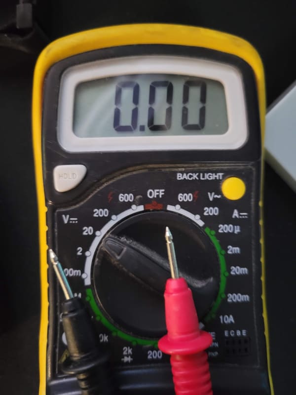
IR, a quality meter with very high impedance will float around a bit with the leads in open air. Once the leads are shorted the meter will clamp down to zero. You're also in the wrong range for this type of test. Even at 480V you should still be using the mV scale.
 
Nope, same effect on mV scale. How high is "high?" 10 Mohm is pretty standard for DMMs; higher impedances require specialized meters such as electrometers.

One could possibly fake this with a large capacitor in parallel and look to see how quickly the capacitor discharges; that would seem to be a more plausible test of continuity, as well as giving one an estimate of the circuit resistance, based on the time it takes to drop to 1/e of the starting voltage.

TTFN (ta ta for now)
I can do absolutely anything. I'm an expert! faq731-376 forum1529 Entire Forum list
 
Thank you very much for all your comments. There are interesting points made by all.

I would like to ask one follow up question.

if we want to determine if two bars, partly embedded in concrete, are electrically connected for the purpose of ensuring that connected anodes will corrode instead of the rebar, is it reasonable or logical to measure the potential difference and if the difference is less than 0.5 mV it would confirm the bars have continuity (or are electrically connected)? In other words is this a reasonable means to verify continuity, in your opinions?
 
That's unlikely with a handheld DMM, since it doesn't have a sufficient high enough input impedance; there are a number of simple circuits that could be used, like which avoids issues with the DMM resistance measurement.

Nevertheless, checking for stray voltage is probably a good thing, regardless; you never know if someone has managed to tie it to a line voltage, etc.

TTFN (ta ta for now)
I can do absolutely anything. I'm an expert! faq731-376 forum1529 Entire Forum list
 
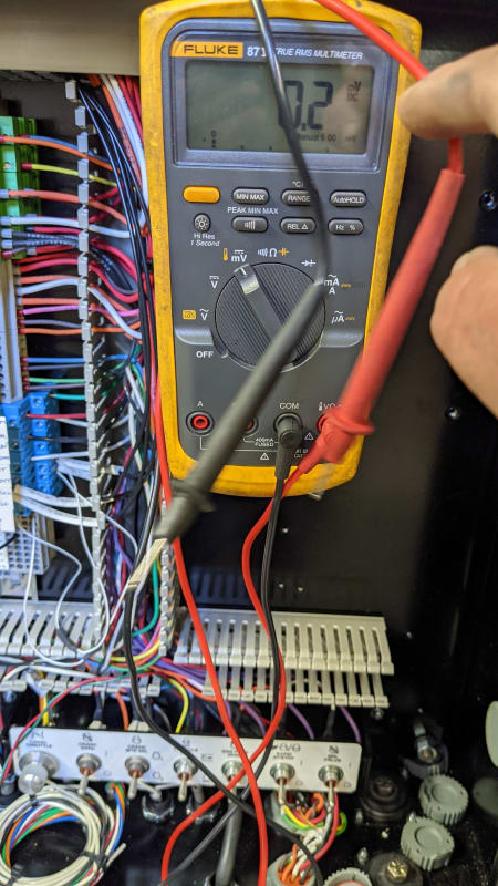
Ok, it settles to zero but any movement of the leads can show up to 3.0mV. Maybe I am just used to a very noisy environment.

PXL_20210603_190722565_lwo9qw.jpg


On a side note, Fluke had a recall a while back. When the meter was placed in the HOLD mode at zero volts it would still show zero when connected to high voltage.
 
Dear Mr gweb
I take it that you wish to verify whether the two different rebars are having good electrical connection.
I am of the opinion that:
1. the mV measurement across the bars is NOT suitable.
Reason being: a) any stray current would show some mV on the DMM,
b) some DMM read some mV even with the test probes separated,
c) some DMM read some mV with test probes separated but in contact with your left and right hand fingers,
d) when DMM reads 0mV or some mV is NOT an indication of low contact resistance across the contact points.
2. A DMM with mOhm range, measurement based on [four-point measurement method] but circulates a very low current [within mA] is also NOT suitable.
3. A proposal measurement by [four-point[ method with circulating current as high as possible say 100Adc but NOT lower than 10Adc. Take down the mV drop. Use Ohm's law to calculate the contact resistance. Reverse the battery polarity to reconfirm the reading. A car battery will do the job. There are uOhm test sets on the market. The important thing to look out for is that the current (preferably dc) shall NOT be lower than say 10Adc.
Che Kuan Yau (Singapore)

 
They said that they use a multimeter selected to DC volts and any reading taken between two reinforcing bars of less than 0.5 mV confirmed continuity between the bars. Does this make sense?

Yes this makes sense as why would the same conductor have any voltage potential difference between points on it. (low frequency)

There are caveats however, one of which is called "contact potential". Dissimilar metals touching can create small voltages. Your probe tip will be a different material than the rebar.

To work this your meter needs to have a relative or zero function. It's fairly common. You'd measure between two immediately adjacent points on the same piece of rebar. This can be 1mm apart. If you measure any voltage, and you probably will, watch it to make sure it's not varying. Move one of the probes a few times to see if it's repeatable leaving the other probe completely unmoved. Consider using an alligator clip on the fixed probe. If yes, then use the zero or relative function to zero the meter. Now WITHOUT moving the fixed probe AT ALL take the other lead to the other neighboring rebar and check the potential. Indeed if you get less than 1uV you can consider them to be electrically connected.


Depending on how small a resistance your DMM can measure you can also do this same exact process using the ohms measurement feature. This will actually drive a current thru the structure showing the quality of the interconnect. There are things that can mess this up some so you need to reverse connections to see if you get identical readings. If not then more investigation will be needed.


Keith Cress
kcress -
 
Some additional comments on contact potential.
There may be mill scale on the re-bar
Continuity between bars may be by the tie wire of a different grade of iron than the re-bars affecting the contact potential.
There may be a capillary layer of concrete between the re-bars affecting the contact potential.
If there is contact potential, it will bias the Ohms reading, hence the need to reverse the leads and check the Ohms at both polarities.

Bill
--------------------
Ohm's law
Not just a good idea;
It's the LAW!
 
Status
Not open for further replies.

Part and Inventory Search

Sponsor