Continue to Site

Eng-Tips is the largest engineering community on the Internet

Intelligent Work Forums for Engineering Professionals

  • Congratulations KootK on being selected by the Eng-Tips community for having the most helpful posts in the forums last week. Way to Go!

Continuity effects and beam torsion

Status
Not open for further replies.

marc.rogue

Structural
Jan 23, 2020
23
Hello,
I am interested in finding literature or a simple way to use distribution factors or continuity effects to distribute torsion in beams along a beam line on a parking garage.
 
Replies continue below

Recommended for you

I've heard it said that shear and torsion are close cousins -- such that relationships of shear load and reactions in indeterminate structures will approximately hold for torsional loads.

Apply sound engineering judgement as needed.

----
just call me Lo.
 
If in a parking garage, the beam should be made of reinforced concrete and bounded by columns. The torsion within a span will not pass beyond the end supports.
 
Hey retired13, to be honest with you that's exactly what I thought but I have come across a few things that make me think otherwise. Lets say in an equal exterior line of beams lets say separated by 3 columns the torsion should be identical on all of them but I have received a frame analysis which show the outer most beam receiving most of the torsion. I immediately imagined there must be some continuity effect that is distributing the torsion along the beam line.
 
Was that a 2D or 3D frame analysis? How was the torsional restraint of each beam to column connection modeled? If all three columns are identical and the beam is prismatic, then I would be curious to see if there's either a beam framing into to end columns (90 degrees to the beam being considered) or there are some torsional constraints set at the ends of the beam. In either case, it would alter the support's torsional stiffness and "attract" more of the load. In a purely elastic, uncracked sense it seems you'd get more at the middle support if all else is equal. Maybe it accounts for some stiffness reduction for cracking at the center support?
 
I believe this phenomenon was not due to distribution between beams, but rather the influence from the load source (the floors). I wouldn't say I am 100% positive, but remember that for uniformly loaded continuous beams, the first interior support will yield higher reaction!? I think the two cases are similar in nature.
 
Is the exterior beam the only one part of a moment frame? Where the interior beams merely support a slab and have no back span beam?

If so, this may be a case of the rotational / torsional stiffness of the exterior beam is so much more than the interior beams that it's attracting more load.
 
I believe is was a 3d frame analysis, no additional beams framing into the column. The reason im bother by this its because I have to design for torsion reinforcement in these beam and the outer most beams have a ridiculous amount of torsion compared to the center beam. I just find it hard to believe that any change in support conditions and what not would change the torsion between the center beam and the outer beams by more than 82%. The system being used is a combination of precast and cast in place
 
Can you post a quick sketch? Might help us envision what's going on.
 
OP said:
I immediately imagined there must be some continuity effect that is distributing the torsion along the beam line.

There absolutely is such a continuity effect, particularly when considering uncracked, elastic torsion. In most cases, however, your beams will crack torsionally at ULS loads and that should be considered as it will have the following impacts:

1) Torsional stiffness in a torsionally cracked beam will drop massively. One the order of 90%.

2) Beams are likely to be torsionally cracked near their ends but not near their mid-spans. So forget anything resembling straight TL/GJ.

In most structures, compatibility torsion redistribution principles will apply and taking advantage of them will be the practical way to prosecute your design. That, rather than trying to track elastic torsion through the structure accurately. Sometimes I do worry that beam torsion will manifest itself as underestimated column moments.


OP said:
The system being used is a combination of precast and cast in place

I'd not yet seen this statement when I posted my own. This may well not be a situation in which compatibility torsion applies.
 
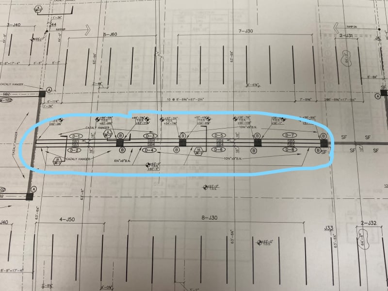
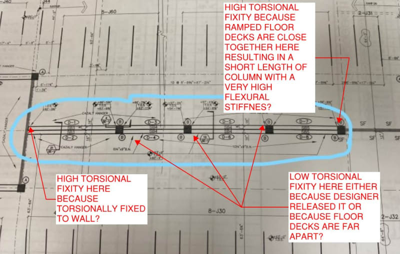
This is what im looking at guys, mind you this is not a double line of beams the beam on the upper side are sloped going up with the ramp grade. I didn't design this myself but I know the way it all comes together essentially the beam will be left an inch from the column face and then the slab beam an column will be casted monolithically.
Inkedtorsion_LI_acsop9.jpg
 
Do you have access to a plot of torsion across the entire line?
 
Unfortunately I do not, I have the torsion values from the frame analysis. Torsion on beam d-2 and d-8 is considerably more than d-4 and d-6
 
Was the load case consisted of uniform load on all spans? How about dead load only?
 
I see where you are going with it retired13 but it was all distributed loading
 
Ok, let's check one thing. Use an uniform torque of 1 k-ft and multiple the entire length (all spans), and compute the torsional reactions at supports by linear interpolating. Then compare the resulting magnitudes, and see if the ratio agree with the computer output or not.
 
OP said:
Unfortunately I do not, I have the torsion values from the frame analysis. Torsion on beam d-2 and d-8 is considerably more than d-4 and d-6

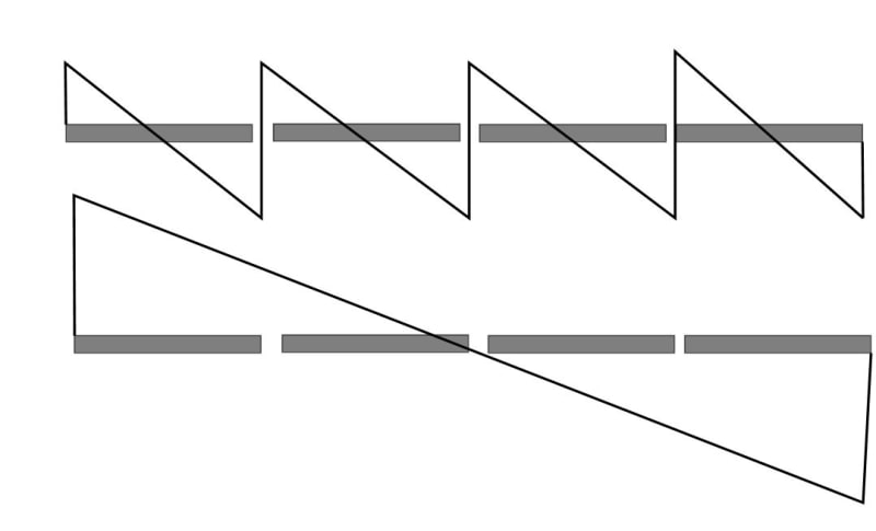
Tough to diagnose the model without a good look at the model. We don't have the first condition shown below which is what you seem to have expected. From the raw numbers, can you tell if we might have the second condition below? If so, that might go a long ways towards an explanation.

c01_eylhw7.jpg
 
ok lets say that linear distribution of torsion along the span is what's happening, is that even a realistic way of thinking about this assuming that the beams are prismatic and the stiffness everywhere virtually the same? To answer you question Kootk yes we can assume is distributed like your second condition and that yes the ratios match like retired13 suggested. What is the reasoning behind this approach? some continuity effect like my original suspicion?
 
Status
Not open for further replies.

Part and Inventory Search

Sponsor