Continue to Site

Eng-Tips is the largest engineering community on the Internet

Intelligent Work Forums for Engineering Professionals

  • Congratulations waross on being selected by the Eng-Tips community for having the most helpful posts in the forums last week. Way to Go!

Continuity From Existing To New Wood Diaphragm 5

Status
Not open for further replies.

STrctPono

Structural
Jan 9, 2020
703
I've mentioned before that I don't do a lot of wood design and I have always gotten very helpful advice from everyone in the past. For that... I appreciate you all.

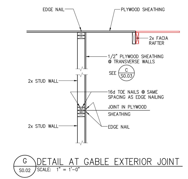
For a typical scenario where you would be doing a gable roof extension off of an existing roof with 1/2" plywood. What is the best detail for providing continuity from the new diaphragm (shown in red) to the existing diaphragm? Would you use a collector element or is there a way to strap the diaphragms together at discrete locations? The new structure is small and will not have its own lateral force resisting system and will need to engage the existing structure. Rafters run in and out of the page. I'm worried about forces occurring left to right.

Thanks!
Collector_sboxns.png
 
Replies continue below

Recommended for you

I like to require the roof stripped back at least 5 or 6 feet so the plywood sheathing can be lapped in with the existing. This provides much better continuity and removes the cross grain bending that comes from just butting it up and fastening the joists together.

If this doesn't work or makes everyone too angry, at least removing the roofing back just past the gable end wall, verifying sheathing fastening in that region to make the overhang a cantilevered diaphragm and then size the connection of the rafters to transfer the in plane shear. For out of plane you could specify straps and blocking.
 
I agree with everything phamENG wrote. I tend to have them pull it back roughly 4 feet. That typically gets you to the first interior joist/truss. Sometimes I still end up needing to sister a nailer there with screws because I haven't had a whole ton of luck getting the guys to cut the existing sheathing exactly halfway over the joist/truss.
 
Rip the existing plywood back (as others have suggested) so that you can stagger the plywood as opposed to having a continuous joint. I like having that sistered joist at the transition as well. If you needed to you could clip it all the way down, but I think the plywood stagger and continuity is your main resistance.
 
Thank you all. On threads like this where I have a little experience (but not enough to comment authoritatively) I like to evaluate what my personal solution would be, then lurk a bit to see what others (with more experienced voices) say.

Just an example of how this forum does a good job at improving my knowledge and confidence.

 
Thank you everyone! I feared that was going to be the answer. It makes sense, however.

The eave is a 30" overhang. The existing structure has pre-engineered trusses at 2'-0" o.c. on the existing building side and we are stick framing rafters on the new side at 2'-0" o.c.

So is the consensus to rip the plywood back to the first truss line (2'-0" inside the gable end wall) and splice it there?
 
I'd rip it back and try to get a 2:1 ratio (similar to backspan cantilever action) if possible. It all depends on where the trusses are and where the plywood joints end up.
 
I don't know if I'd go 2:1 like skeletron says, that seems a bit overkill to me. But without seeing the whole thing it's tough to comment. My personal feel, is if the diaphragm has enough capacity to cantilever past the end of the building, then you just need to make a confident splice into it and make sure that all of the aspects are accounted for, including chords and where that load is getting moved to the ground.
 
I shall be the massively dissenting opinion on this one I guess. I think that strctPono had exactly the right idea in his first post with one, minor exception: I'd remove the overhang and fasten the sistered piece to the wall top plates as that is likely the designated shear transfer location for the existing diaphragm.

Without pulling any punches with respect to taking the sheathing back beyond the exterior wall:

1) It strikes me as punitive, excessively so.

2) I believe that it is largely pointless and, perhaps, a failure to recognize the nuances of the shear panel assumption that we make when doing wood diaphragm design. We design these diaphragms assuming no axial force in plane.

3) In my opinion, the sheathing is butted along a single line at the wall and the real issue is what needs to be done to get meaningful chords for the new diaphragm. Some options:

a) Collectors extended into the existing building which can be very difficult to prosecute or;

b) Shear walls in the addition perpendicular to the wall shown in OP's original post.
 
Without pulling any punches with respect to taking the sheathing back beyond the exterior wall

Is that really what people were saying? I heard someone say "roughly 4ft", which made sense to me. That allows you to get full plywood sheets in so that the diaphragm is more of a "continuous" diaphragm rather than having a seam in it. At least that's how I interpreted the comments.

It's just that because in this case, we have such a short overhang (30"), it ends up being basically the same thing.
 
JP said:
Is that really what people were saying?

Yeah, I believe so. All of the comments that I see above amount to taking it inboard of the exterior wall.

JP said:
It's just that because in this case, we have such a short overhang (30"), it ends up being basically the same thing.

In the context of a residential structure of this sort, 30" is actually a fairly long over hang. Most are in the 12" to 24" range.

JP said:
That allows you to get full plywood sheets in so that the diaphragm is more of a "continuous" diaphragm rather than having a seam in it.

Certainly. I imagine that the intent is to develop some tension capacity across the diaphragm joint in a similar manner as to how shear is transmitted across 2x members in unblocked diaphragms and, thus, shield the sistered member from cross grain bending. And I'm sure that does happen to some degree when that strategy is employed. That said:

1) Most of what we do in wood diaphragm design is predicated upon avoiding the transmission of in plane axial forces in sheathed diaphragms. In this respect, I don't feel that this tension ought to be relied upon for calculation purposes.

2) In my opinion, the real feature of the addition that, hopefully, shields the sistered piece from cross grain bending is as a favorable aspect ratio of the addition diaphragm between collector elements. Stiffness tends to be the antidote to most structural compatibility problems.
 
In principle, I'm not even opposed to making the shear attachment at the fascia board, particularly if the sistering member is a truss top chord. My concerns with that pertain to my expectation that the fascia board is a 1x that lacks full boundary nailing.
 
I'd be more concerned with the hinge in the wall.....
 
XR250 said:
I'd be more concerned with the hinge in the wall.....
Wow, good catch. Yeah that's scary. Especially with the sheathing joint specified right there as well.
 
I assumed that the "hinge" was probably already braced by something existing and that it simply wasn't shown in this detail. Kickers, ceiling gypsum... something. Perhaps also substitution with a gable end truss.
 
Status
Not open for further replies.

Part and Inventory Search

Sponsor