milkshakelake
Structural
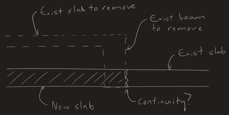
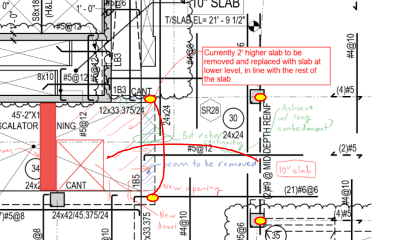
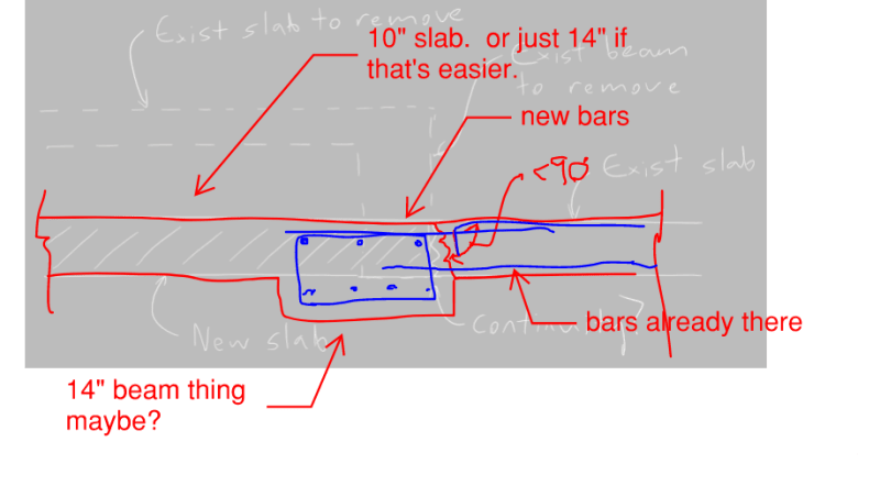
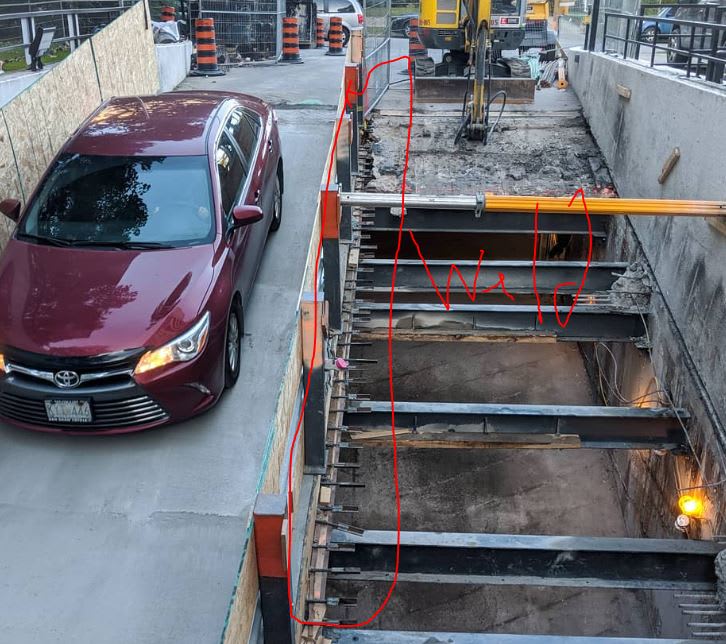
I'm extending a slab. Removing an old slab that's 2' higher than the rest of the floor level, and leveling it out. Do I need to worry about continuity?
I could look into alternative schemes like adding beams, but that will affect headroom. I prefer to extend the slab. But extending it means doweling pretty far in to achieve correct development length. For #4 rebar, it's like 24" doweled in. It's pretty far. I'm not confident that a hammer drill will nicely make the extremely long hole and not crack the underside/top of the slab.
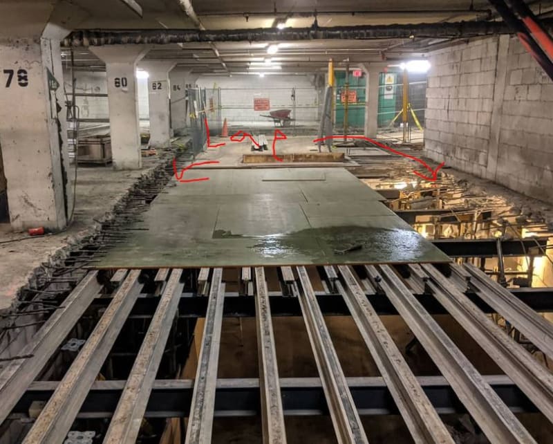
In terms of continuity, the bottom rebar will be equally important, if not more important, than the top. The top will develop a column strip and some middle strip (negative moment), but if that fails or it doesn't properly develop, the bottom needs to be 100% carrying the load.
The other thing I'm worried about is shear, which will be transferred solely through the new dowels. The more I think about it, the more it seems like a bad idea. Hopefully someone can point me in the right direction.

I could look into alternative schemes like adding beams, but that will affect headroom. I prefer to extend the slab. But extending it means doweling pretty far in to achieve correct development length. For #4 rebar, it's like 24" doweled in. It's pretty far. I'm not confident that a hammer drill will nicely make the extremely long hole and not crack the underside/top of the slab.
In terms of continuity, the bottom rebar will be equally important, if not more important, than the top. The top will develop a column strip and some middle strip (negative moment), but if that fails or it doesn't properly develop, the bottom needs to be 100% carrying the load.
The other thing I'm worried about is shear, which will be transferred solely through the new dowels. The more I think about it, the more it seems like a bad idea. Hopefully someone can point me in the right direction.