Continue to Site

Eng-Tips is the largest engineering community on the Internet

Intelligent Work Forums for Engineering Professionals

  • Congratulations KootK on being selected by the Eng-Tips community for having the most helpful posts in the forums last week. Way to Go!

Continuity issue by extending a slab 1

Status
Not open for further replies.

milkshakelake

Structural
Jul 15, 2013
1,116
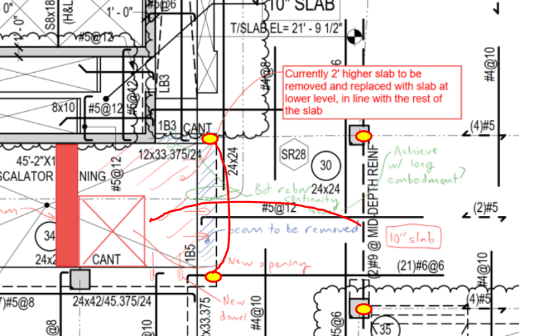
I'm extending a slab. Removing an old slab that's 2' higher than the rest of the floor level, and leveling it out. Do I need to worry about continuity?

I could look into alternative schemes like adding beams, but that will affect headroom. I prefer to extend the slab. But extending it means doweling pretty far in to achieve correct development length. For #4 rebar, it's like 24" doweled in. It's pretty far. I'm not confident that a hammer drill will nicely make the extremely long hole and not crack the underside/top of the slab.

In terms of continuity, the bottom rebar will be equally important, if not more important, than the top. The top will develop a column strip and some middle strip (negative moment), but if that fails or it doesn't properly develop, the bottom needs to be 100% carrying the load.

The other thing I'm worried about is shear, which will be transferred solely through the new dowels. The more I think about it, the more it seems like a bad idea. Hopefully someone can point me in the right direction.

Screenshot_2023-11-28_113823_x9frbb.png
 
Replies continue below

Recommended for you

So the existing, upper level slab bit never was really continuous with the adjacent slab, correct? If so, I think that your proposal would work. Design the infill as pinned and put some top steel in around the perimeter for crack control and to enhance shear transfer.

Where will the soffit of the new slab land, vertically, relative to the soffits of the beams that will support it? It would be nice if the beams projected a bit below the new slab.

For shear, worst case scenario you can probably bolt a bearing angle on to the supporting beams and take the shear through that.

 
So the existing, upper level slab bit never was really continuous with the adjacent slab, correct?

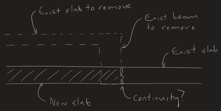
Correct, it was connected to an upturned 24x24 beam (marked in blue) which the adjacent slab was also connected to. This beam will need to be demolished. I made a little sketch below:

Screenshot_2023-11-28_140643_cvcb7t.png


Design the infill as pinned

Without beams under it, it would have to be designed as continuous. I'll try to see if I can convince the client to add a beam exactly under where the old beam used to be. But it'll rob them of 2' of headroom on the floor below so I'm not sure it's an option.

Where will the soffit of the new slab land, vertically, relative to the soffits of the beams that will support it?

I think you're assuming I'll add beams, but I'm trying to explore an option where I don't. Trying to get a sanity check. My first idea was also a beam, but it comes with architectural issues...
 
@Smoulder Is that possible? It would take a jackhammer crew a few days, and I'm afraid there will be pieces of concrete stuck to the exposed rebar.
 
We’ve done that a few times. It can be done but there’s always the risk of them “accidentally” cutting all the bars off, and then you’re back to glueing on bars.
 
just as a tangent-is there a way to continue a slab without reinforcement without a cold-joint? any books on this side of cosmetic cementing?
 
MSL said:
I think you're assuming I'll add beams, but I'm trying to explore an option where I don't.

You are correct. I must read gooder.

MSL said:
For #4 rebar, it's like 24" doweled in. It's pretty far.

And that may not even be enough. Properly restoring continuity means creating an offset lap splice with the opposing bars, not just developing the new bars.

MSL said:
But it'll rob them of 2' of headroom on the floor below so I'm not sure it's an option.

It's a pretty short beam span. 16'-ish? Not sure if it helps but it probably doesn't need to be a 24" deep beam. Surely something in the 16" range or less would suffice.

MSL said:
Without beams under it, it would have to be designed as continuous.

Not necessarily. You could design the infill pinned at the joint, the existing as an edge condition receiving a line load from that, and use the dowels to enhance shear transfer and control cracking. I don't know if the numbers would check out but the load path is certainly there.

MSL said:
In terms of continuity, the bottom rebar will be equally important, if not more important, than the top.

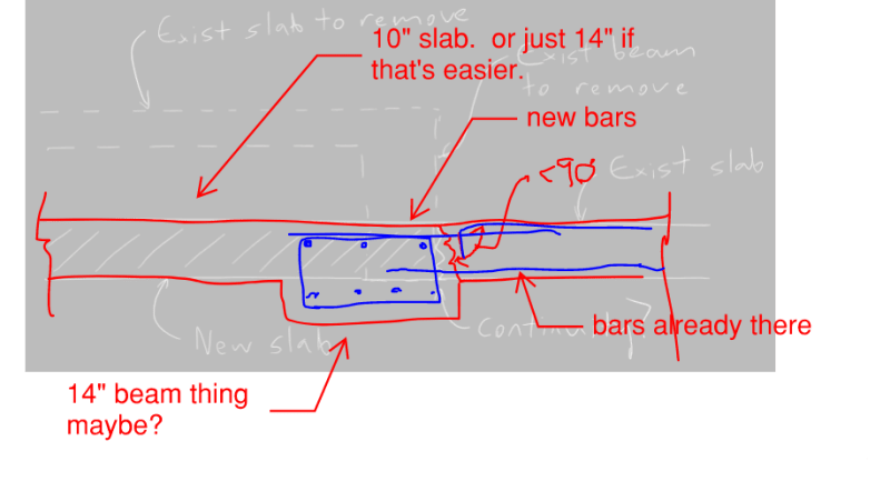
I'm not sure that I agree. When I look at the slab, I see four had spots as shown below, with reinforcing patterns that jives with that. I bet that original beam wasn't doing a whole lot more than taking up space.

c01_nf2nh3.png
 
Sell them on something like this and I'd think that you'd be off to the races.

c01_jrkogn.png
 
@Tomfh Yeah that's a major issue that I see. Even with a skilled operator, it's really hard to do it without accidentally breaking the rebar.

@KootK Thanks! This is probably what I'll end up doing. I kind of assumed that a heavily reinforced 24x24 beam was needed because of 100 psf live loading, but now that I think about it, those kinds of dimensions are generally what I use for transfer beams holding up 6 stories or something. A small beam might suffice. Instead of running FEM, I might be able to put some triangular loading or even half-tributary-width loading and call it a day. No issues with long-term deflection with that span. And also thanks for the idea that I could just apply the loading as pinned. I haven't thought of that. I probably won't do it because I don't think it'll work with the existing slab rebar, but it's a neat idea.
 
I think KootK has you on the right design path but I did want to chime in with some of your concerns with practicality.

Epoxying Bars

Bars can absolutely be epoxied in 24" without issue. I've done that on multiple projects where we couldn't lap to existing and welding wasn't viable. However, you will want to A) enforce the use of dustless bits / vacuum setups and B) only do this with contractors your trust. The dustless part is essential because it's very hard to properly clean a hole of that depth with conventional means (mechanical scrubbing + compressed air blowing). For these kinds of operations we would usually have Hilti on-site during the installation procedures. I've never had a problem getting their technical reps out to do this, but I also buy a lot of epoxy so I'm not sure how easy that would be for your contractor to do.

Chipping for a lap

We chip slabs all day long for laps in Toronto. There are zero concerns about this being an issue unless you get into chasing delaminated concrete. What happens is we sawcut a 1/2" deep line at the edge of the repair using a straight edge & quick cut, then use 30lbs hammers to chip up to 2" - 6" in front of that line, and complete final chipping with the 15lbs hammers. Obviously larger areas we use hoe-rams and the like, but for small areas a pneumatic chipping hammer works great.

Existing bars are usually cleaned via sandblasting. If that's an issue you can mechanically clean them via a wire wheel. Wire wheeling is more tedious procedure, and the wheels are expensive, but it is done when sandblasting is prohibited.

EDIT - you can restrict hammer size in your demolition notes to reduce the possibility of damaging existing bars, especially near supports. If you don't usually some guy will take a 60lbs hammer right up to the column or whatever, and that can cause problems. I have typical notes for this if you want a gander (but my post is already so long and bloated that I wont add more unless you want lol).

Welding

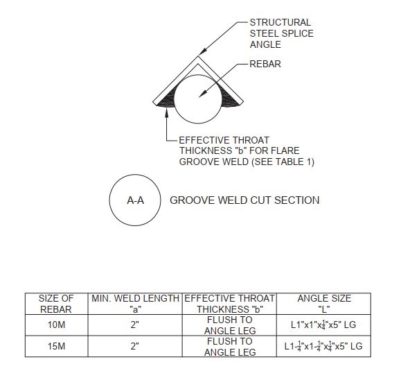
If your steel is of weldable grade (and sometimes even when not) then you can weld your splices instead of chipping and lapping. This works well for a small number of bars where lapping is not possible for whatever reason. I used to specify an effective throat less than bringing the weld flush to the angle leg (since that's technically all you need) but for practical reasons, mostly hard to inspect exact effective depth, we have gone just flush to keep it simple.

Pic_4_lutsum.jpg


pic_6_xhkd0m.jpg


Shear Transfer

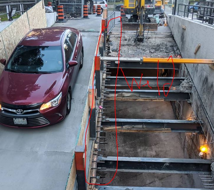
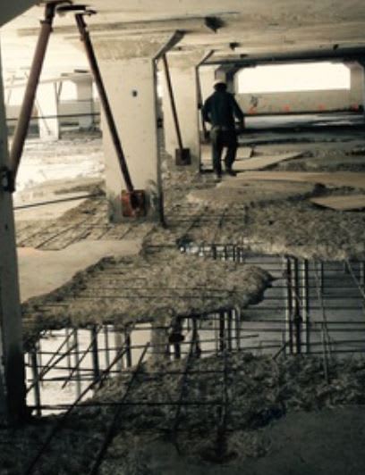
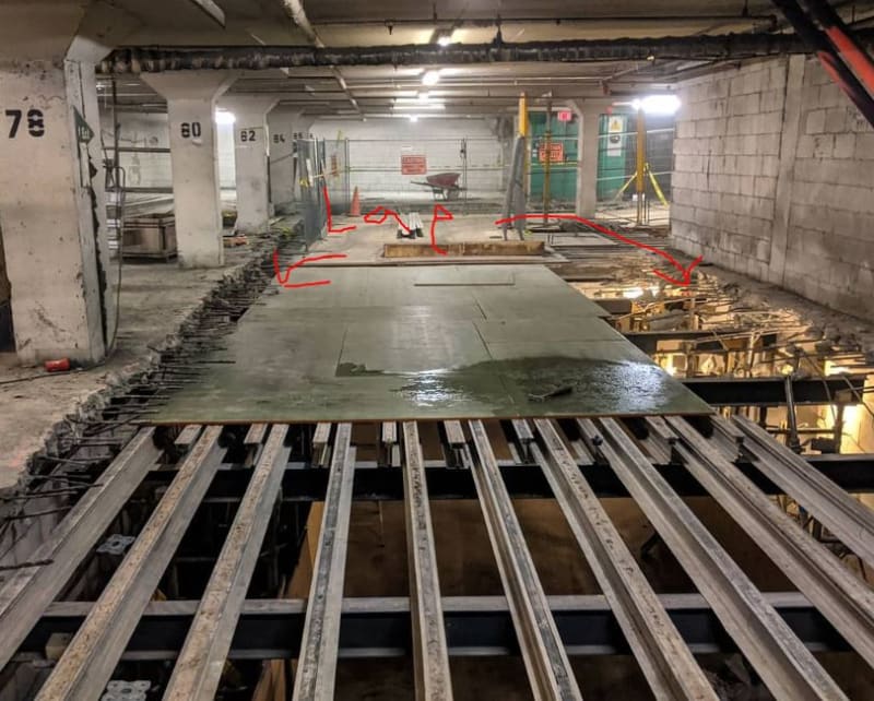
Yeah, not ideal of course. But to help you sleep below are a few pictures of mixed topside / through-slab repairs. Not much special is done about this other than some mid-slab bars to promote dowel action and use of SikaTop EpoCem as a bonding agent. Only when you chip to vertical supports do we get fancy with haunches, angles, chipping a seat into the existing, etc. Not saying that this is "right" just that it's done every day in Toronto and I have not heard of a problem or failure with shear transfer at repair extents.

Pic1_hgqpva.jpg


Pic3_gvsj9p.jpg
 
That’s wild. What state are the slabs in to warrant that level of destruction?
 
lexpatrie: Canada also has a lovely problem with mixed units. Welcome! We buy reinforcing steel by the metric ton but go across the street to buy structural steel by the imperial ton. Where the guys on site have imperial tape measures but our designs are in metric so we are pressured to produce imperial drawings to "aid constructability". Where the old drawings are full imperial but new drawings submitted for permit on government jobs are only accepted if they are metric. And where our wood products are almost always in imperial except for some large suppliers who want to change the world so they stock metric equivalents, but they are not identical, so it completely messes up the spacing on-site for large runs.

Tomfh: Mostly exterior slabs cast in the 60s - 80s that are exposed to deicing salts (e.g. parking garages, balconies), which were not waterproofed during original construction. Sometimes deicing salts were used on the forms so we have to repair those as well; these are noticeable because of the massive damage to the soffit but relatively intact topside.

Lately we are getting on to repairing the repairs and have gone full cycle. The mixed topside/through-slab you see in the second last picture in my previous post is usually the result of a cheap owner who doesn't want to go full replacement. Instead they go for Hydrodemolition (topside only) and the blow-throughs become through-slabs. It's never ideal and hopefully after such a large number of blow throughs you can convince the owner of the life cycle return of going full replacement. But sometimes that is shut down quickly.
 
lexpatrie said:
that mixed metric/english drawing is giving me convulsions.
I'm glad I'm not the only one. I rarely get involved in concrete design/construction like this, but I still figured I'd be able to read a damn framing plan. I assume that the labels are referring to concrete beams, joists, and slabs? Are the hooked end of lines depicting hooked rebar at beams/walls?
 
@Enable Thanks for the responses. I'll be sure to specify that a dustless/vacuum setup be used if I do the 24" thing. I'm not keen on the contractors this client uses, so I'll have a talk with them.
About chipping out the concrete, the client raised a concern about noise. There are existing tenants in the building (medical, gyms, etc) so they want to avoid chipping hammers & try to stick to saw cutting only. So I might do the drilling thing anyway. Thanks for offering your demo notes! I probably won't need it for this project, but I always appreciate sharing of proprietary stuff like that. Not everyone is willing.
About the steel welded splice, that's for when you can't get enough of the rebar to stick out for development length, right? It's like using a coupler. Seems like a good idea I'll keep in my back pocket.
About shear transfer, I agree that some bars in the center of the slab thickness should do the trick. I was thinking of a crazy idea, that I can restore shear continuity using expansive repair concrete or repair mortar along with an epoxy bonding agent. Kind of like a weld or epoxy glue, but for slabs. I'm not sure such a thing is possible. But I'll look into the Sika product and alternatives, and see if what I'm imagining is a real thing. Briefly looking at the product specs, it seems viable, but I'll have to call them.

@lexpatrie That article is pretty wild. I didn't know you could drill that far. It's also funny how they used a helicopter instead of a crane for material delivery for cost savings. I thought helicopters were a millionaire's club thing. You learn something new every day.

@Eng16080 If you're referring to the drawing snippet I posted, it's all imperial. You mean Enable's one? Yeah, I have no idea what 10M or 15M rebar is. Sounds like #3 and #4. It might be a Canadian thing to do it in this way.
 
milkshakelake, I was referring to your drawing. To be fair, I've never designed an elevated concrete floor which didn't rely on metal deck and steel beams for support, so I'm perhaps not familiar with the conventions used on drawings in this case. I would guess that "1B5" is a beam label, and "LB3" is a lintel. Are "24x24" and "12x33.375" also beam labels? If so, why the different convention?

(Feel free to disregard if off topic. Was just curious.)
 
Yeah, 1BX is a beam label (first floor, beam X). Something like 12x33.375/24 is a beam that starts at 12x33.375 and ends at 12x24, so it's like a stepped beam. 24x24 is just a differently dimensioned beam; width then height. The dimensions are given as well as the beam label because it's useful to see the size of the beam on plan instead of referring to a schedule. It's not my drawings, but I use a similar convention. Concrete drawings aren't all bad to read, this one is just particularly weird.

I personally use a convention like CB1(12x33.375/24) and omit the floor number, so everything is concretely tied to one beam schedule. I also don't use B1 because there might be other types of beams (CFS or wood) in the drawing, especially with buildings on concrete podiums, so it's specifically a CB.
 
Thanks milkshakelake. That makes sense. I appreciate the explanation.
 
milkshakelake: No problem on the notes feel free to reach out if you ever need. You are correct about the welding being used when lap lengths are hard to come by, and they are indeed a replacement for couplers. In restoration we wind up finding all manner of old style bar, which makes couplers a problem since we don't know what we need to couple to until we've demo'd...and we generally don't want to wait, so we call a welder and it's done in a day. Since it's our go-to approach we tend to use it even when couplers might work. It is more versatile and forgiving to variations in existing conditions.

For the welding it's always best to shop weld the new bars to the angle. It allows for quicker welding, better welding, and easier inspection. Only field weld the one side to the existing bars. Perhaps if you have 2 splices to do then maybe it might be less headache to weld entirely in the field, but if you have 20 then, yeah, field and shop mix is the way to go.

FYI when we demo in commercial spaces around here it's usually night work. If you have a commercial base + residential tower then we generally get permits for extended hours on weekend work. But if you must go near zero noise then saw cutting (or coring) is probably the way to go.

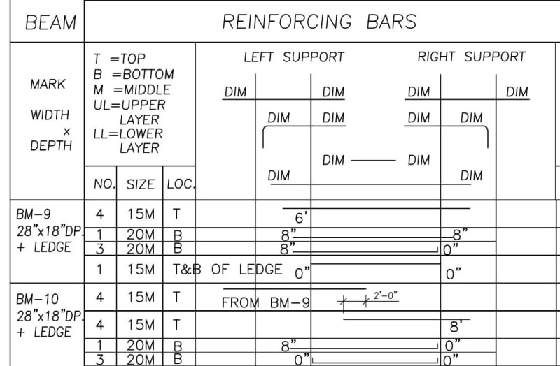
P.S Here's a beam schedule that'll send some in this thread into an epileptic shock. This is Canada!

Beam_Schedule_nh6dxd.jpg
 
Status
Not open for further replies.

Part and Inventory Search

Sponsor