Continue to Site

Eng-Tips is the largest engineering community on the Internet

Intelligent Work Forums for Engineering Professionals

  • Congratulations waross on being selected by the Eng-Tips community for having the most helpful posts in the forums last week. Way to Go!

Continuous Polyline in Drafting

Status
Not open for further replies.

JRMorton

Mechanical
Jul 14, 2015
11
US
Hello,

I am trying to setup ply patterns for a gerber cutting machine. I have my ply patterns defined in CATIA Drafting. This drawing will be output as a DXF file for the gerber cutter to read.

The way the gerber cutter works is that it will route and cut my prepreg material per each line or curve defined by the template. However, each time a line or curve terminates on the template, the knife on the gerber cutter lifts up. If the ply pattern has numerous short lines or curves on the template, this will result in the knife lifting up and then cutting down for each single line or curve. This amounts to a longer and less efficient cutting routing.

I would like to turn a number of connected lines and curves into a single continuous smooth polyline, so that the gerber cutter reads it as a single curve and will cut in a single stroke the entire curve in a continuous stroke without having to lift up the knife then place it back down again for each of the numerous lines and curves that defines that profile. General Surface Design has a function that allows to smooth and join curves, is there a similar option for Drafting? If not, is there a way to output the template I defined in Drafting into GSD, then smooth and join the curve and then output it into Drafting so it will recognize it as a continuous polyline?

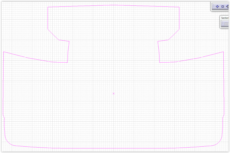
In the attached picture, the very top curve is split into two so the gerber cutter would cut from the left side of that curve, then lift up the knife and then place it down again to cut the second curve on the right. If the two curves that make up the top curve were one smooth curve, the gerber cutter would cut that whole curve in a single stroke without having to lift up in the middle. I need a way to join these lines to minimize the amount of lifting of the knife to make the gerber cutter process more efficient.

Thanks to anyone that can help out.
Screen_Shot_11-20-15_at_10.06_AM_ncvhia.png
 
Replies continue below

Recommended for you

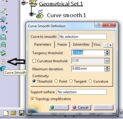
you can use curve smooth option. i use it all the time when i export plies for cutting
 
Thanks Jenial. Is this done in the Drafting or Composite Workbench? I modified some of my plies manually in the drafting workbench since the CATIA generated ones were not 100% accurate.
 
do you have a cpm license? i guess it's also available with extended surface design license.
 
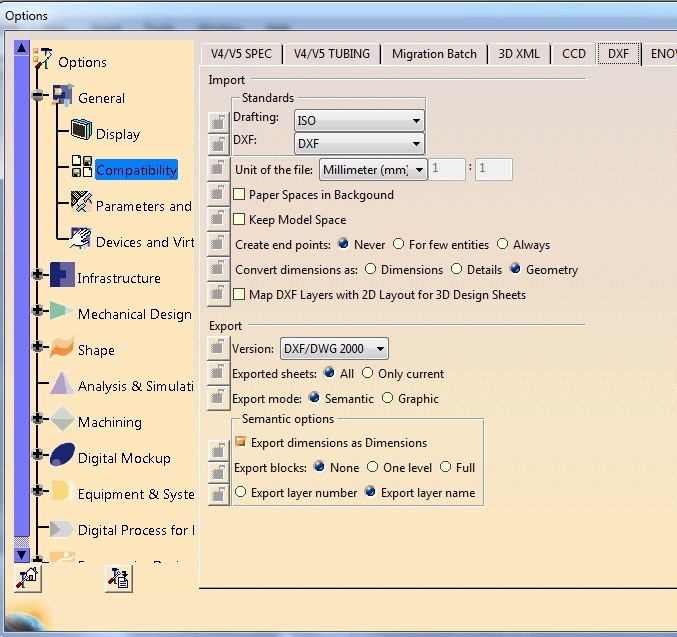
in tools option make sure you have :
Mechanical Drafting // view : project 3d wireframe
compatibility // DXF : select export mode: semantic

copy view and paste view in 3D to get sketch
project sketch into new drawing by making front view

save drawing as DXF

that will give you a block in dxf

Eric N.
indocti discant et ament meminisse periti
 
itsmyjob it's not about a block. i'm familiar with what he is talking about. the only way to make gerber jump less is to use smooth curve.
in CPM this will be done in a few seconds for all the plies

JRMorton if you don't have too much files i can help you with that, so we can see if it works.
 
Hello JeniaL,

I do not see a CPM option under my licenses, so I do not believe I have it. However, I do have CPD and under Composite Design workbench I have Manufacturing tools such as Excess Material, Skin Swapping, and Prepare for Synchronization. Are there different tools between CPD and CPM that will be required to create a smooth curve?

We are laying up on a female tool and have a MEOP scribed into our tool. When we layed up the CATIA generated ply pattern, it was in some areas 1.00 in. off. We put our CATIA generated flat patterns into a drafting drawing, measured and recorded from our tool's MEOP how far off it was; then in Drafting manually drew what the pattern should actually look like based on our measurement, reference off from the MEOP scribe line.

That being said, our master ply patterns are in a Drawing rather than in a CATPart. So it is preferable to be able to smooth our curves in the Drawing. Does CATIA allow you to adjust and locally change the flat patterns it generates in the Composite Design Workbench?

I managed to work around the issue of creating a smooth continuous curve by copying my Drawing View into a CATPart (it came in as a Sketch), then extracting the lines that I wanted to connect, then joining them and using "Curve Smooth" function under GSD. After that I projected it back into a Drawing. If there is a faster simpler approach, it will be very helpful since CATIA generated plies are very rarely 100% accurate, especially for parts with varying curvature in them.
 
in most cases catia creates very accurate flat patterns. this depends on producibility settings/seed point.
try to look in commands for curve smooth. i guess this operation comes from extended surface design.
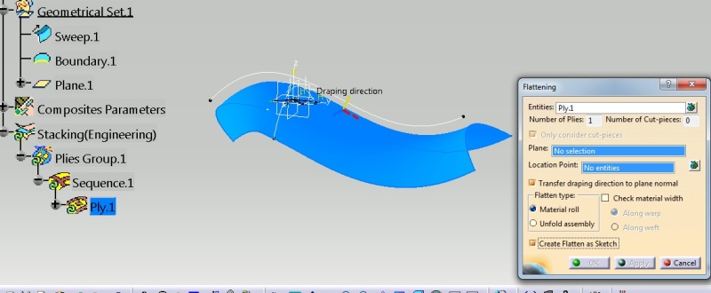
in composites look for a flatten optimization command.

to get rid from editing in drawing check create as sketch box when you use flatten command. this will give you an opportunity to edit plies inside sketch workbench hovewer this will not prevent from having a contour from hundreds of pieces.
Untitled_g3zheq.jpg

Untitled2_twscae.jpg


upload several of a bad plies. i'll fix them and we'll see how gerber eats that.
 
Thanks JeniaL, I'll upload a few plies later today. One more issue I have to resolve to get my patterns working on my gerber cutter is the following:

My ply patterns are in a Drawing as previously stated. In the drawing, I have named my ply and placed the text inside the ply. I want my gerber cutter to write the ply name on my plies to facilitate kitting. When I save my drawing as a dxf file, my gerber cutter program (CutWorks)does not recognize the text as text, but instead as part of the ply. It recognizes the text and ply pattern as one layer, instead of the ply pattern as one layer and the text as text (it wants to cut the text and ply pattern, it only allows for selection of one tool instead of giving two separate tool options, one as knife and the other as a pen).

Another programmer that helped us set up the machine was using AutoCAD and was able to use my dxf file to assign two different layers, one to the ply pattern and the other to the text. The text was assigned a text layer. This worked with the gerber cutter and allowed the pen option. He also ran into a similar problem as I did when he used text to write inside the ply (the gerber cutter wanted to cut the text), but he played with different fonts and eventually found one that the program recognized as text.

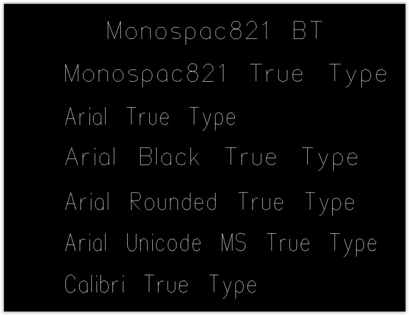
So my question is the following, what is the best text to use in CATIA with a gerber cutter so that text can be recognized in a dxf file?
 
first you need to change some setting. check semantic mode. in my case i use don't export blocks. we use Eastman cutter.
Untitled_x3cxmi.jpg


maybe if you check export blocks as one level will work for you.
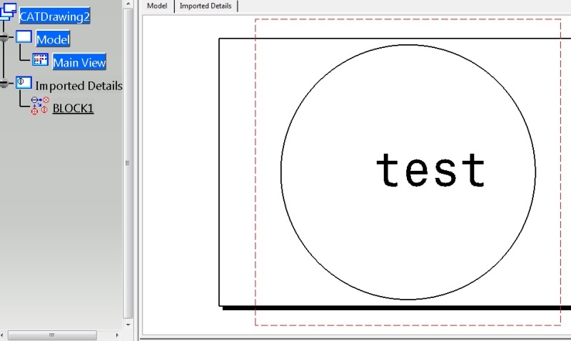
see how dxf looks in catia with export as one level option on.
Untitled2_e4szci.jpg


with Eastman it took me awhile to find right setting.
 
back to block...

Eric N.
indocti discant et ament meminisse periti
 
Hello JeniaL,

Changing my settings to be just like yours worked. Thanks.

Is there a way to smooth the lettering using dxf? When my program reads the dxf file, it chops the lettering and its not smooth as it looked in CATIA.

Screen_Shot_11-25-15_at_10.11_AM_vsuvdo.png


Screen_Shot_11-25-15_at_10.12_AM_gfvvg6.png


I tried different fonts and the same thing happened. Thanks again, you've been very helpful.
 
welcome.
i don't think you can smooth the text while exporting. look for some settings in your gerber software.
as for me, no matter what font i use, our Eastman software changes it. i don't really care if my font smooth or not. it's just a label on a ply.

how is plies smoothing going?
 
Status
Not open for further replies.

Part and Inventory Search

Sponsor

Top