Continue to Site

Eng-Tips is the largest engineering community on the Internet

Intelligent Work Forums for Engineering Professionals

  • Congratulations waross on being selected by the Eng-Tips community for having the most helpful posts in the forums last week. Way to Go!

Continuous Slab Ledge to Exist CIP 2

Status
Not open for further replies.

Brad805

Structural
Oct 26, 2010
1,490
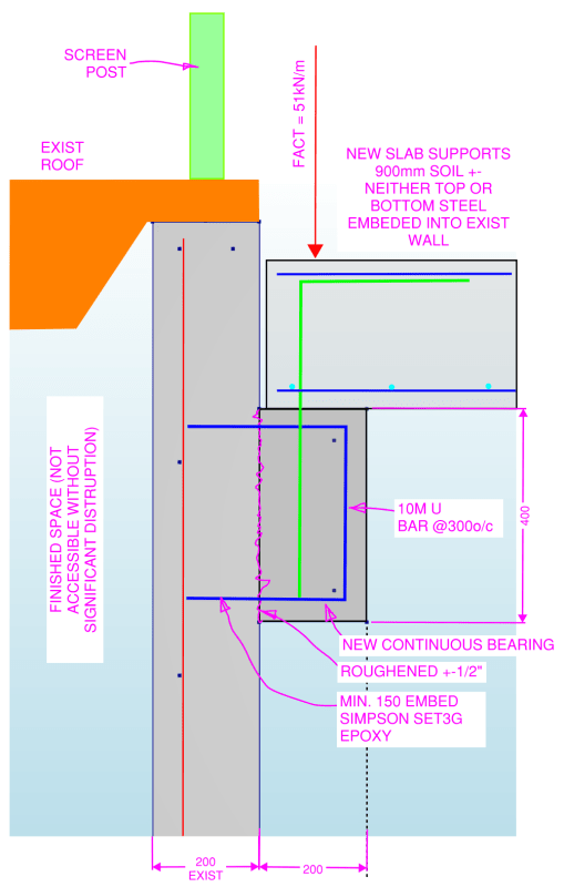
I was asked to offer an opinion on the suitability of the detail below. They are planning to build a tunnel adjacent to the existing building. The tunnel will have a slab over it that supports 900mm of soil. I was only asked to comment on the continuous slab ledge. I would prefer to see a 40mm bearing surface for the new slab, but they are not too interested in changing the detail. In general the numbers do seem to work, but reading Joel's thread I thought I should seek others opinion on the field drilling/epoxy anchorage.

WALL-LEDGE_cdlksm.png


Corrected sketch
 
Replies continue below

Recommended for you

I've been playing engineer for over 50 years and although I work in both, I think in imperial and have to mentally convert metric to imperial to comfirm that it works... just a bit of a dinosaur. By using the angle and blueskin, you can make a real waterresistant joint. The 1/2" gap from the angle acts as a bit of void for the caulking, but IMHO is too narrow and you want to widen the top to about 1" to accommodate any movement. [pipe]

-----*****-----
So strange to see the singularity approaching while the entire planet is rapidly turning into a hellscape. -John Coates

-Dik
 
Greenalleycat, I see your point about the restraint. I have tried a few options:
1. Fixed wall head. This would be problematic for the existing wall since it would see some moments it is not designed for. Looking at the original bldg dwgs, the existing structure does not have a slab as I suggested earlier. It is a light weight roof and the green part in the sketch is a screen post. I do not think a fixed head is applicable.
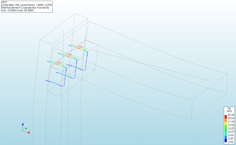
2. Pin wall head. For the forces to increase as you described I had to allow the slab to deform laterally in the XX direction. Given the slab will be supported on a new wall right of the sketch, I am not sure this would happen. Nonetheless I ran the model, and the force in the critical tie would increase from 21kN to around 29kN (sketch below). This is not feasible as you thought.
3. Wall head free/slab fixed XX at middle. This was the original model.

I chatted with the EOR, and they are amenable to the bearing detail. It turns out the new wall option was discussed at length, and the owners were adamant against it.

I thought about Dik's suggestion a little more and it made me think of another project where we were working. In that case, they installed around 900 kwik bolts and sat many long span double tees atop. I thought the idea was crazy, but I had nothing to do with it. As greenalleycat mentioned, how would the bearing ledger really differ from a technical standpoint? Where is the cutoff point for a detail like the one suggested? I do not like the epoxy solution for this, but we all live in the real world.

The fine print for the Simpson products is a bit different than Hilti's in regard to the sustained load question, so I reached out to them for their opinion.
WALL-LEDGE-4_f456gn.png
 
Nicely done mate, sounds like you're doing your job properly

Figuring out the real load in this case is tricky
It's one of those ones where you can work out a minimum load and a maximum load and know that the real load lies somewhere in the middle depending on how much restraint the slab edge actually gets from the corbel

I personally don't worry about epoxy in creep super much these days, as long as I'm specifying the top-shelf epoxies
I wouldn't use the lower quality epoxies in any kind of creep application though

I will say I have used basically the same detail as Dik has mentioned on quite a few jobs, though most often with cast-in inserts rather than epoxy
Fundamentally this still has the same effect though, it's just a bit more reliable with cast-in inserts
This is often with precast floors, where a 100mm flat slab will be dropped onto the angle and then a 100mm topping (or whatever) is poured on top of that
So there is no direct connection of the precast unit to the angle to form an unintended moment - they sit on bearing strips
This makes it pretty straightforward to calculate an eccentricity and design the bolts for a primary shear and a tension from the eccentricity of the floor load

I agree it's hard to know when it is/is not appropriate to use a detail such as this one - to be honest, if this wasn't supporting 900mm of soil I'd probably be fine with it
It's just a gut feeling that a better option should be used here as it's a hard to inspect, hard to maintain detail that is sitting under a lot of load and has potential for long-term moisture ingress (there's a real weak point there, you're fully reliant on tanking to ensure your hairpins into the wall don't corrode in time)
It's also a tunnel, so if anyone is in there one day then it will be certain death for them if it fails
 
I don't support the corbel detail as I mentioned above but, at the same time, a 400 mm deep corbel would surely have much more capacity than a 4x4 ledge angle. Right?!? Maybe the ledge angle could do the job but, given where the client's at with this, I think that it would be spurious to propose that solution as being more capable than the corbel somehow.
 
@KootK, I agree with you
I think the only advantage the angle has is not to induce a restraining moment...but that can just as easily be accomplished in the corbel by removing the dowels between corbel and slab and putting a bearing strip on top as someone (you?) suggested earlier

I suppose the angle does have the advantage of allowing access to the bolts in the future but this seems not super useful

 
As detailed, the dowels were just a crap setup to begin with. If there are to be dowels for lateral connections, those would probably be better placed into the wall, perhaps with a foam sleeve on them for a certain length or something.

Another problem with the angle is that the best way to do that is to turn the vertical leg upwards. And, then, you're back to not having any ability to inspect it meaningfully.
 
I had no intention of suggesting the angle. This is a tunnel in a winery, and they would never want to see a speck of steel. I was mainly pondering the difference and seeking others thoughts.

I appreciate all the help and advice.
 
Thanks Koot... the leg is nearly always upwards... that way the blueskin can be clamped and used as a water barrier.

-----*****-----
So strange to see the singularity approaching while the entire planet is rapidly turning into a hellscape. -John Coates

-Dik
 
If this were my detail I would put a 20mm thk strip bearing in as others have mentioned. You can drill holes in it for the vertical dowel...or relocate the dowel and run it straight into the wall (horizontally into the slab).

When they say 'soil'...do they mean they will be compacting it to 100% proctor with a 30000lb roller? Probably not.. but there might be a construction load case that may govern the design.
 
Why the objection to a new wall? By the time you get all this done to build a proper corbel, even if the existing wall is strong enough, the new wall would be paid for.
 
I agree hokie. The reasoning seemed somewhat odd given it is just an access tunnel to get to a wine room cave. They seemed to have a problem losing the 6" of space. I did not follow. I have worked with a few of these wine facility owners and I have found some have their own ideas and most have the $$ to get what they want. I am sure the engineer argued his point as best he could.

The soil fill is to be loose. It is to be placed with an excavator sitting beside the slab, I was not advised of any heavy equipment or traffic on the slab.

With a bearing surface for the corbel, the force in the critical corbel tie drops to 3kN each (model) and approximately 5kN each with a simple hand calc. In the model the interface used has a shear component between the corbel and wall face, and hand calc does not. While the detail is still not great, I am not sure there is a technical reason it does not work. If I were faced with the same problem at the design stage I would have likely used a larger bar and tighter spacing if I could not persuade them to add a new wall. I like a safety margin equal to about 3-5 for something like this.
 
I lose sleep on the epoxy because I don't think the holes are ever prepared per Hilti or Simpson's instructions. I attended a Hilti webinar a few weeks ago and the Hilti rep said that if a hole isn't cleaned properly then the epoxy anchor can lose 70%+ of it's capacity.

But....I don't lose as much sleep about shear keys. If the rebar holds, then the shear friction generated at the joint is off the charts.
 
@Joel this is why I say to test them to keep the contractor honest. They may save money on the anchors...BUT they will need to test a certain number to ensure they are doing them proper...which may offset the $$$ to do epoxy or scare the shit out of them.

I never spec epoxy anchors without having atleast one tested...I think it is $40/hr plus mileage for a tester so usually $200-300 doesn't break the bank. And if it does I walk.

I would have to say even IF the contractor knows you MIGHT test the anchors they WILL do a better jobs than if you dont say you may.


Status
Not open for further replies.

Part and Inventory Search

Sponsor