Continue to Site

Eng-Tips is the largest engineering community on the Internet

Intelligent Work Forums for Engineering Professionals

  • Congratulations KootK on being selected by the Eng-Tips community for having the most helpful posts in the forums last week. Way to Go!

Contractor forgot hairpins in foundation 1

Status
Not open for further replies.

8bitEng

Civil/Environmental
Sep 22, 2023
7
Hi All, I'm looking from ideas/input on this issue. I'm on a project where the contractor forgot to place the rebar hairpins at the top of the concrete columns for a per-engineered steel building. The error wasn't discovered until months after the building was complete and photos of construction were being reviewed for record drawings. Per design, the hairpins were to prevent break out of the bolts. As it currently sits, the capacity of the bolt connection is under capacity by 4kips, breakout is the failure mode.

On one side of the building, the foundation was poured against another per-engineered steel building foundation so the top of the piers are restrained by the foundation/slab of the adjacent building. Would this potentially prevent bolt breakout as the concrete between the bolts and edge of pier is unable to move laterally due to the adjacent building?

On the opposite side, the piers are not restrained by an adjacent building. Could a steel plate/beam or whatever is needed to resist the breakout force be placed across the outside face of the concrete pier to restrain breakout failure? Does concrete breakout function linearly or would breakout occur and push up?

Thanks for your input.
 
Well that's a bummer. Who did the rebar inspections?

Against the other building...as long as it's tight, I'd be okay with it. Just make sure the as-built drawings clearly indicate that it's relying on that other foundation.

For the free side...I'm not sure what you could do short of extending the foundation out beyond the limits of the building and anchoring it in really well.
 
Maybe you could weld on a base plate extension towards the interior of the building and add some post-installed anchors. I’d want something in writing from the PEMB designer signing off that the frame is not adversely affected by the added anchors, or something along those lines.
 
You probably want to explore other options first, but there can be ways to add rebar to the slab if your column and slab geometry allows access.

See attached link to an article in Structure Mag.

The author details how hairpins were added to support a balcony railing post. That's much smaller scale than your issue, but I think the concepts are the same.

Link

Capture_xeybqj.jpg
 
The city did the inspections and obviously missed this. Also, the contractor did realize their mistake because they ended up epoxy setting half the hairpin into each side of the pier prior to the slab being poured which the city did not call for special inspection. The EOR was not notified of this change and obviously this did nothing in reducing breakout.

I'll take a look at that article. It may be a possibility but the hole that would need to be drilled would likely be 4'+ in order to get through the pier and into the slab.
 
8bitEng,
Are the top of the concrete piers flush with the top of concrete slab or do they stick up? Roughly, what is the size of the steel columns and how far apart are they spaced along the exterior wall?
 
Eng16080,

The top of piers are flush with the interior slab. The base plates are approximately 12"x 12" and the steel columns are spaced at ~25' o.c.
 
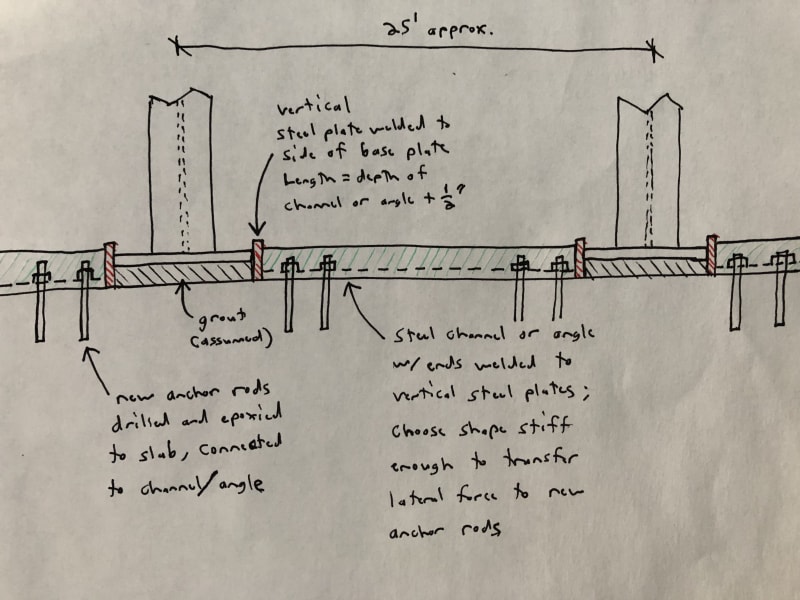
Not sure if this works for your particular application, but here's an idea:
hairpin_fix_tibfog.jpg

Basically, run a steel shape between the base plates. I figure a channel or angle probably works best. The lateral force from the columns will be transferred into the steel shape which will be attached to the concrete with anchor rods drilled and epoxied. You'll want to choose a steel shape stiff enough to transfer that force to the new anchor bolts which are located furthest from the column. If you only need 2 or 3 new anchors at each end, a relatively small shape should work.

Modifications on this idea might also work, like extending wings off the base plate or column to provide more anchor locations, without extending the shape all the way between columns.
 
I'm surprised to hear the city did the inspections, normally this is mandated per chapter 17 of the IBC which requires the EOR to specify the SSI.

Could you provide a detail showing the intended installation, you will get better responses with such detail?

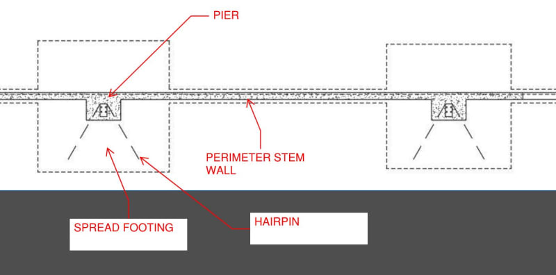
You say concrete columns in your original post, am I correct in assuming these are pedestals sitting on a spread footing with a turndown between said pedestals?

FRP may be an option as FRP is great in tension. You would want to contact an FRP company like Quakewrap, to discuss the options. The two possibilities I picture are placing FRP to restrain the breakout on the face and top, this may be difficult to quantify and develop; the other I'm wondering if there is some kind of attachment of FRP to the base plate where you can essentially connect the baseplate directly to FRP and extend FRP strips on top of the slab as if they are hairpins. This may require coordination with the PEMB engineers, which I highly doubt they would be willing to assist with. Regardless I don't see this being a cheap fix, I wouldn't surprised if a 3rd party consultant fee would be more than your fee to design the foundations.
 
Can you sketch how the pedestals sit in relation to everything?
 
There was no epoxy set specified on the plans so no SSI needed for this but the contractor did their own thing. In the past,the city calls for SSI if it's not specified on the plans and is needed/required.

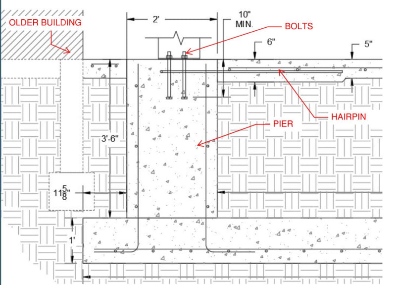
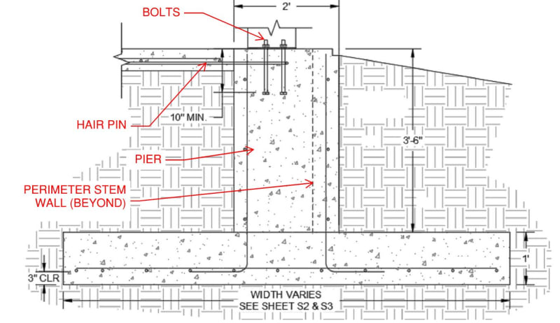
You are correct, it's a pedestal sitting on spread footings. Below is some sections details of the pier next to the original building and the opposite side. Also, below is a plan view of how the piers are set with regards to perimeter stem wall.

F1_lwvtqa.jpg
F2_rm11xk.jpg
F3_licefg.jpg
 
I assume there is pier reinforcing installed, with closely spaced ties near the top. See if you can get the ties to calc out as anchor reinforcement using the Widianto strut and tie method.
 
As for SSI, I suggest taking a look at chapter 17 of the IBC, epoxy isn't the only inspection required. Epoxy is one, but cast in place anchors also require it, structural steel for the PEMB requires it (and normally this is specified by the EOR), depending on concrete strength the design mix, reinforcement placing, excavation etc. require special inspections. For a building such as this, it is my opinion that SSI for all concrete was most likely required per code. This is besides the point however.

Does the pedestal have ties? How close are the anchors to the edge of pedestal?

What is the thrust force?
 
What's the magnitude of the load that you need to resist?
 
Thanks for the advice, I'll review that section for future plans.

The pedestal does have ties. If I recall correctly, edge distance is around 8-9inches. I'll have to verify when I'm back in the office. Shear varies with frame line but max is around 22kips.
 
8 to 9 inches is a decent amount, maybe there is a way to make the concrete edge distance work, however with anything over about 10 kips, you are normally hard pressed to get hairpins to work, normally at 22 kips you would have needed tie beams. Not saying you can't make hairpins work, but at 25' o.c. the influence areas overlap before you grab enough concrete typically to resist due to friction/weight.
 
16kips is what I can get out of the edge distance. Hairpins were to supplement to rest.
 
Dedicated anchor reinforcement should be designed for the full 22 kip shear load, not the net load after subtracting the breakout capacity.
 
What was your uplift force?
 
Status
Not open for further replies.

Part and Inventory Search

Sponsor