Continue to Site

Eng-Tips is the largest engineering community on the Internet

Intelligent Work Forums for Engineering Professionals

  • Congratulations KootK on being selected by the Eng-Tips community for having the most helpful posts in the forums last week. Way to Go!

Contractor will not provide rebar shop drawings? 11

Status
Not open for further replies.

Ben29

Structural
Aug 7, 2014
316
I did a fairly simple project. It is a 1,500SF,1-story addition to an existing building. The foundation consists of strip footings and slab on grade with WWF. Our general notes require that rebar shop drawings are provided. Our General Notes read: "if shop drawings are not provided then our firm is not responsible for the structural certification and design of the project."

The architect told me that the contractor does not plan to provide rebar shop drawings. The architect asked me, "Are you OK with that?"

How do you answer this question?

They do plan to have a 3rd party inspector inspect the rebar placement.
 
Replies continue below

Recommended for you

I always think pretty hard about things that I require on my drawings because it gets really awkward when you relax the requirements later. If they're going to ask if they can omit, you allow the relaxation, and then something goes wrong it looks like you didn't meet your own standard of care. If you just didn't require it, then them making a mistake is on them. I generally try to give a justification for the relaxation or ask for something to mitigate it.
 
Greenalleycat said:
Man, you guys do stuff weirdly!
We would never do rebar shop drawings - the closest we would ever come is reviewing drawings for precast concrete panels

Where I work in Canada it is commonplace to get rebar shop drawings. Aside from very few simple projects where the contractor asks if they can use our foundation drawings as the shop drawings, we require rebar shop drawings to be detailed.

Brad805 said:
To do clash detection would take endless amounts of time

You mean you just place your anchors on the drawings willy nilly and don't check if they actually fit within the grade beam with the prescribed covers? How do you ensure that the rebar gets enough cover, or that the anchor has enough edge distance then if you don't check if it even fits properly?

TLHS said:
I generally try to give a justification for the relaxation or ask for something to mitigate it.

This is the way.
 
EngDM, no, that is not what I am saying. Those are basic design issues. I am suggesting the time to compare the rod buster shop dwgs with all the various trades takes a lot of effort. It is not what I see being done. One can have clashes with mechanical blockouts, electrical items, architectural details and any number of other things. Most have generic details for those. A set of rod buster drawings for a decent sized pour can be a 20-100 pages and they are designed to be concise for the field people. I do not see a lot of markups suggesting much of that is being checked.
 
If anyone cares... from the point of view of a GC, not producing shop drawings and not having them reviewed is nuts.

Strongly agree with Eng16080/JAE/XR250/others regarding the overall purpose of shop drawing review - to ensure the details have been correctly interpreted by the GC, concrete sub, and bar fabricator.

I can't speak for every GC... but in my orbit, rebar shops are no different than any other submittal; an engineer's review does not absolve me of complete responsibility for conformance with drawings/specs/code/whatever. If an engineer misses a bend detail or whatever that's wrong, and we catch it in pre-pour, it's still my problem to fix. If it got missed by the EOR and installed, that means me and my guys missed it twice. It's on us.

Greenalleycat said:
The process here is to produce structural drawings showing what is required,

No offense intended - but if you're telling me that you produce drawings sets for large, complicated projects which show every single possible configuration of many various concrete encapsulated assemblies in sufficient detail for rebar crews to order, tag, and tie bar using your drawings alone.. I don't believe you. Every single job I've ever build with significant concrete had SOME sort of clash, or issue with embedded utilities next to a column or thickened edge, or penetration not shown on structural, or whatever, that was caught at some point between rebar shop review and GC side trade coordination. That's why we do it, so it doesn't get caught on pre-pour when it's too late. Not to mention that I've never seen a structural drawing which had each individual bent bar identified with a piece code, which is an absolute necessity for a large complicated reinforcement design, and gets done as part of the process of producing the shops.

Greenalleycat said:
Amazing that you guys are so trusting of your contractors

You're putting WAY more trust in your contractors by not requiring them to show you the plan before they start ordering bar. To me, and it seems to most of my colleagues in the states, that's crazy. They review shops specifically because they DON'T trust me to get it right. And I'm perfectly fine with that attitude because the stakes are high. I will never turn down one more opportunity to catch mistakes before the money has actually been spent.

Greenalleycat said:
Why are you inspecting with the trucks lining up and why are you getting blamed if they fuck it up

No one is performing a pre-pour inspection day of, unless we're talking about a very small pour.

And if you are inspecting day of, in our world you've already looked at the shops so you have at least some idea how competent the GC is at all the required coordination.
 
I have practiced as both an engineer and a contractor in both North America(NA) and Australia. The conditions Greenalletcat is talking about relate to the norm in AU/NZ where the engineer's construction documents near-fully detail the reinforcing steel such that shop drawings are not required for building structures.

The GC sends the EOR drawings to his rebar supplier, they schedule/cut/bend the rebar, and the steel fixers (aka rod busters in NA) install. The EOR does not get a rebar shop drawing to review.

The EOR in AU (used to) undertake his own rebar (pre-pour) inspections too. If it was a complicated arrangement it was common for them to occur over several days as the rebar was being installed (I am thinking of raft foundations, or complicated transfer floors).

For DOT bridge work (I worked on a large cable stayed bridge in AU) the engineer's drawings were of such detail that they included all rebar tags, bend schedules etc. Simply take it to the rebar supplies for scheduling/cutting/bending.

It has been more than 10 years since I have undertaken any AU work, so the standard of AU engineers drawings may have changed, but 'back in the day' I never saw - as an engineer on some projects, and contractor on others - any rebar shop drawings.

Now for NA projects - it would be an absolute disaster if the rebar supplier did not produce shop drawings, except for the most simple of projects. I just completed a minor project with small 16" square pedestals and had to product a rebar shop drawing.

So it is horses for courses...depends on the detail of the EOR's drawings and regional practices.
 
For DOT bridge work (I worked on a large cable stayed bridge in AU) the engineer's drawings were of such detail that they included all rebar tags, bend schedules etc. Simply take it to the rebar supplies for scheduling/cutting/bending.

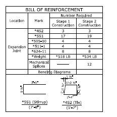
As far as I can tell, our DOT doesn't require rebar shops. We provide a Bill of Reinforcement for each component (generally each piece that will be placed at one time) that includes coating requirements (epoxy coated or plain), bar lengths, the number required, bending diagrams, set diagrams for cut sets, total weights for the bars in each component, and a note that designates a prefix number for the groups of bars (Ensure fabricator prefixes Abutment no. 1 bars with numeral 1, etc.).

Laps not dictated by the bars lengths (i.e. where there's only 2 bars overlapped within a component) are called out in the details; first and last bars in sets are called out, etc. Everything needed for fabrication and placement of bars is in the plans.
 
Ingenuity said:
where the engineer's construction documents near-fully detail the reinforcing steel such that shop drawings are not required for building structures.

If that level of detail is in the CD's, then obviously it changes the conversation. That's a pretty big departure from how we normally operate.

I have a really hard time envisioning getting a set of CDs that are truly comprehensive to build from without any additional detailing at all in between; but if that's how they're doing it, they're obviously making it work.
 
SwinnyGG, some countries are moving in that direction. Here is an example in Norway where no drawings were provided. Norway Bridge It will be a long time until North America goes that route, but some are trying.
 
For regular buildings IFC should be sufficient for both manufacturing and placing of rebar. We model all the rebar in 3D in Revit, then we detail them in 2D and produce rebar schedules based on the 3D model, so all the info is in the model.

As mentioned earlier there are bridges and state run projects in Norway that has been built without paper drawings, not only without rebar drawings, but without any drawings. However, convincing the contractors to do it on design & build projects have been though, so usually we produce the plans, and provide the 3D reinforcement as a visualization tool.

IMO rebar drawings is the easiest part of a project to build from a model, as it's mostly repeating a detail along a line. And for complex details you can visualize it by filtering schedule numbers, rotating, mark with different colours among other tools.

That bridge linked on the other hand requires some serious modelling skills. Those post-stresssed anchors are probably modelled using dynamo (visual programming) or other tools specially made for that project. So they're basically pushing innovation, which is great in the long run, but probably limiting the number of firms capable of designing bridges in the short run.
 
Brad805 said:
It will be a long time until North America goes that route, but some are trying.

They that will happen when the US adopts the metric system, and hell freezes over.
 
Clearly regional differences are the biggest factor at play here

For us, the concrete standards setout the baseline for how steel is done
The contractor has responsibility to comply with those which prevents stuff being grossly wrong (in theory)
Next, all engineering drawings have standard notes and details at the front that replicate a lot of this and basic things like lap lengths etc
Then, typical concrete drawings will include elevations, sections, and plan drawings of the main foundation details so that critical information is conveyed

The complexity of these varies hugely according to the project of course
A house will have one foundation plan and 3-6 details usually
A commercial building will have many more, particularly if it's a concrete framed building
Typically every wall or frame would be elevated with critical information noted - rebar layouts, "don't lap here" and all that
Complex joints - such as a beam-column joint - are likely to be modelled in 3D with bar cranks etc shown - this depends on the job though as to how far this goes

So, not every single thing is detailed, but enough
 
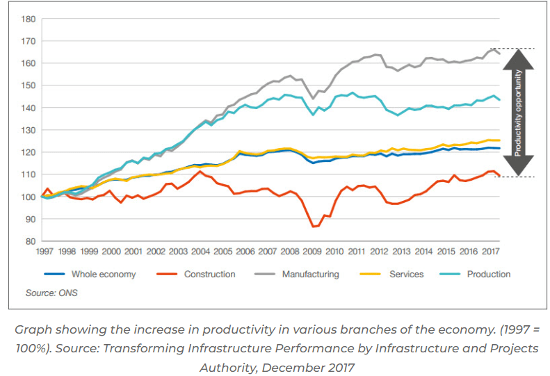
Ingenuity, that is very true. We have a very combative system for a number of reasons. I have attended some integrated project delivery seminars and that looked promising, but it is too difficult to award projects that way. I guess productivity improvements in construction may never change.

productivity_w0dtx3.png


wth, the guy that started that bimcorner site offers a lot of training in the use of grasshopper with different software packages. I have been learning that and it is not that difficult. I can see a lot of benefits in this as you can drive your geometry, analysis and detailing with it. Structured Parametrics has created a number of tools as well. I am not affiliated with either of them.
 
Maybe some examples would help to understand the differences between approaches.

I've attached a 3rd party UK example and found examples from the Philippines and Sierra Leone that look to have a similar approach including the bar schedule full reinforcement arrangements :


and a US set of drawings that omit the bar schedule and reinforcement arrangements beyond typical details


Another contractor perspective (steel fabricator):

The quality of design drawings are declining in my area, leaving many areas of uncertainty. Schedules are getting more compressed, leaving less time for RFI's. We often rely on shop drawing review to clarify design questions that weren't answered via RFI. Another emerging trend is that consultants tend to use our shop drawings as a final check on their design. It is becoming more common that we're seeing markups on our shop drawings for changes to the design, unrelated to any uncertainties that we may have flagged.

I can't imagine doing this work without shop drawings. Its the final chance to say "did I understand you correctly" and "are you sure you want to do this".
 
Ditto what CANPRO said for the steel side of things. I can barely RFI anything these days with the required drawing turnaround by the GC. So to make timelines we do most things in the shop drawings unless things are so uncertain that I cannot proceed without clarification. I bubble / make bold red what I need confirmation on to ensure the EOR cannot miss it.

When I was a concrete contractor shop drawings for reinforcing steel were the norm. However, I never liked them much as they mostly convoluted things and were pretty worthless since I worked in restoration where dimensions are never quite what they were supposed to be. I eventually changed from getting the rebar supplier to do the detailing / bar cutting to ordering stock lengths and cutting as required on-site. Circular ties or large stirrups or what have you I still had them produce a drawing and do the fabrication since those were hard to do properly. Once I switched to this approach engineers that I usually worked with would be fine without shop drawings and we field reviewed everything. Engineers I did not have a history with still required shop drawings which I produced in CAD for them.

As others have said seems to be local practice that dictates. As an engineer these days I wouldn't mind a small slab pour without shop drawings so long as I am doing the physical inspection.
 
Here's a sample of our bridge details and bill of reinforcement. Our spec book and notes cover the rest. For bends and hooks, we reference the ACI Manual of Practice for Detailing Reinforced Concrete Structures.

RC_detail_mixgai.jpg
BOR_example_nmawju.jpg
 
To discuss the drawing quality problem I think one would have to divide the discussion into regions, and market sector. The bridge world always is dealing with authorities that care far more about what they are supplied. Most seem to spend vast amount of time creating standard details they want suppliers or consultants to follow. As a result, I think the quality is better in that market. Now, I have not worked much in that field, but I have found endless examples of details from that sector when researching problems. In the AEC world, the quality is driven by owner's, architects and building officials. All of those vary wildly in what they expect.

The timeline problem we have now is odd. Some deal in reality, some never think things thru and simply ask for something unrealistic and hope for the best.
 
Status
Not open for further replies.

Part and Inventory Search

Sponsor