Continue to Site

Eng-Tips is the largest engineering community on the Internet

Intelligent Work Forums for Engineering Professionals

  • Congratulations SSS148 on being selected by the Eng-Tips community for having the most helpful posts in the forums last week. Way to Go!

Contribution of the Middle Rivet in a X Bracing? 6

Status
Not open for further replies.

Logan82

Structural
May 5, 2021
212
Hi,

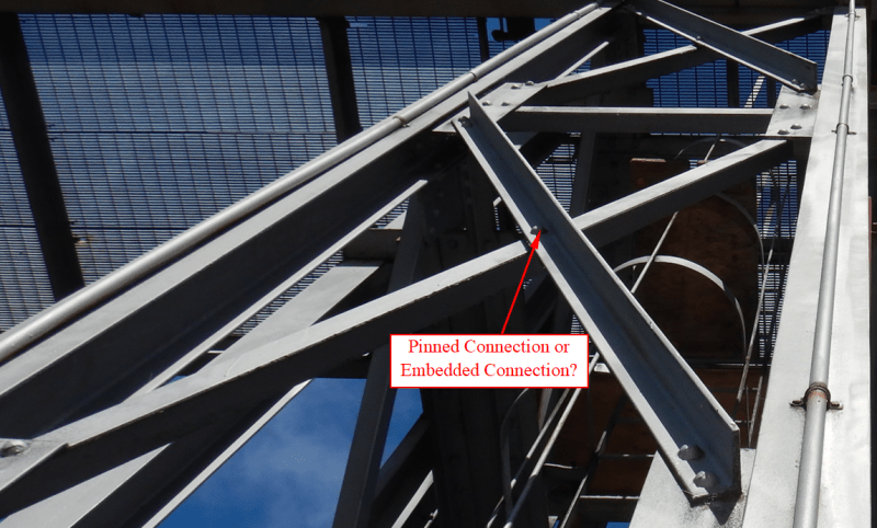
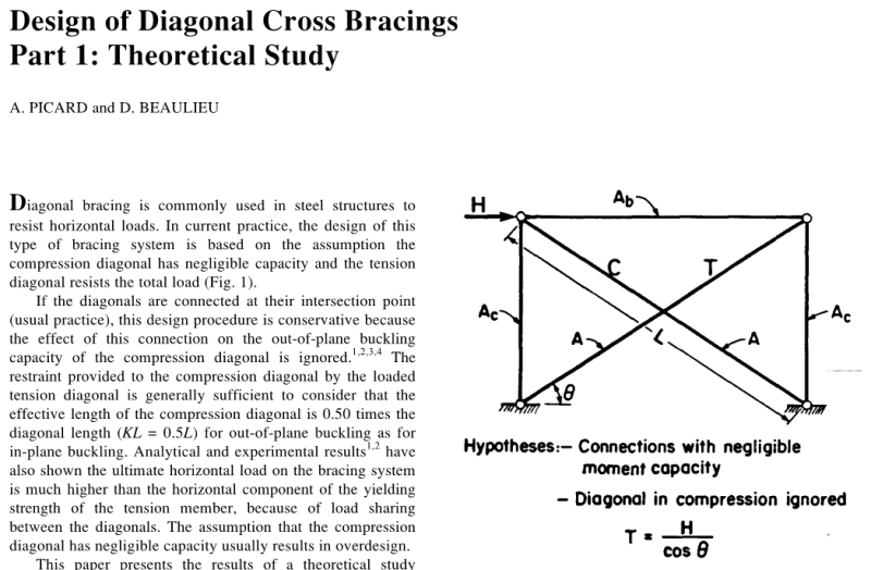
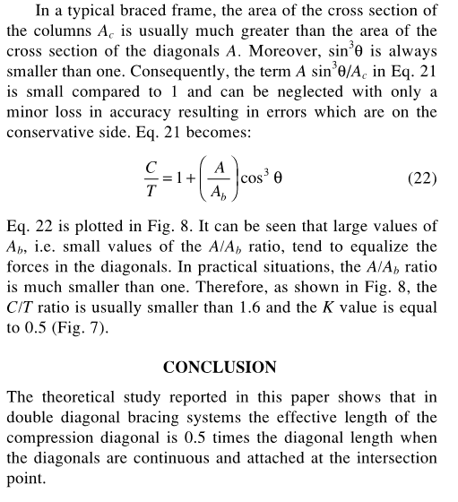
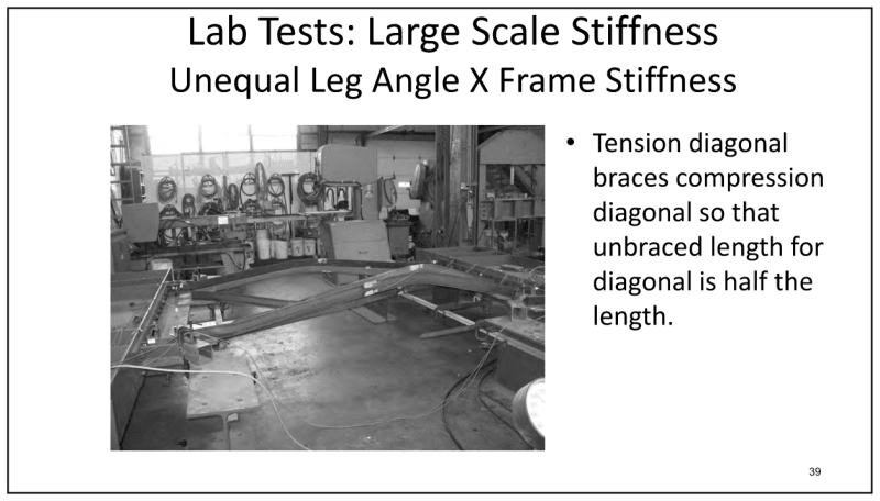
What is the use of a middle rivet in a X bracing? Is it used to reduce the K*L/r ratio? I am asking this because the K*L/r ratio of this bracing is too high (255) if I don't consider the rivet in the middle. I am evaluating this existing structure. It would be odd that the designers at the time (year 1920) would have designed a structure with a K*L/r ratio over 200.
2021-10-26_10_23_49-Window_n8pa4r.png


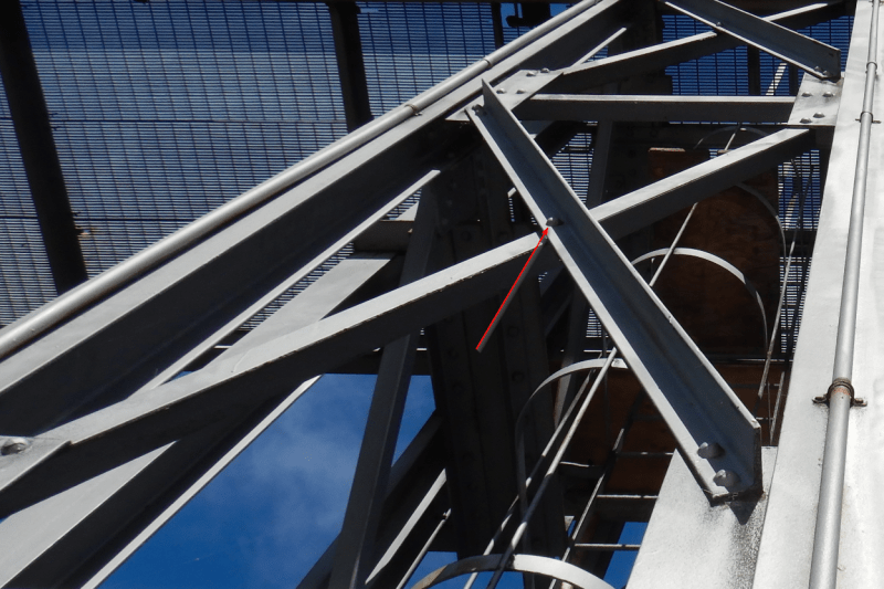
However, I don't see how the middle rivet can really help to support laterally the bracing in compression against buckling perpendicular to the plane of the bracings in X.
 
Replies continue below

Recommended for you

Lots of debate on the effective length thing. Quite a few threads on it. My position is that it does nothing useful in that regard.

Primary purpose is to prevent the angles from slapping against each other in the wind.
 
The theory is that the brace that is in tension will add lateral support to the brace that is in compression if they are pinned together. I'm not as convinced that it isn't useful as phamENG seems to be but I have never looked into it that closely either. I seem to recall reading once that studies have shown that it is effective, but I could be remembering that incorrectly.
 
The aluminum design guide uses 0.45 for an effective length factor. The middle connection also prevents the 'banging' sound from the bracing slapping against the other during wind storms.

Rather than think climate change and the corona virus as science, think of it as the wrath of God. Feel any better?

-Dik
 
It sounds good in theory, but I've looked at it in the context of Yura's bracing theories. To consider it a braced point to reduce the axial length and increase the buckling load it needs to have a certain capacity AND and certain stiffness. Usually, the flexural stiffness of the tension brace is not sufficient to meet this requirement. So you'd have to depend on the tension increasing the stiffness like a cable. Some testing has shown that phenomenon, but as I recall it was not something that could be reliably quantified and/or was not enough to consider.
 
I vote for the bolt, and that connection in general, being adequate to reduce the compression brace kL/r, at least for applications where inelastic frame drift is not expected. I dug deep on this issue long ago and found plenty of support for this in the literature. Unfortunately, I've long ago forgotten just what that literature was or where I might have found it.

In OP's case, I'd be willing to take the bolt as both:

1) Lateral bracing and;

2) Torsional bracing. For single angles this can sometimes be helpful.
 
If nothing else, it prevents the braces from colliding with each other every time the wind changes, with annoying, and perhaps concerning, cacophony of sounds. I was told, many years ago, that the effective length of the compressive brace is halved when the two are tied together. I never doubted it at the time, but perhaps its benefit was exaggerated.

BA
 
dauwerda, do you remember the reference of the study?
That would be very interesting to see.

I tend to be always on the conservative side and I would think that phamENG is right, however I want to verify if there are some clause / studies that could come in a counter engineering study. This is because the cost of replacing those bracings would be big.

I have two practical calculation questions in relation to that middle rivet
1) How would you evaluate if the middle rivet is sufficiently strong to resist buckling?
2) In a FEM software like Advance Design America, how would you consider the contribution of this rivet? I have only two options:
2021-10-26_11_53_45-Window_vczxkm.png

If I select pinned, my model in unstable. If I select embedded, the connection in the middle of the X is too rigid. So the easiest way to calculate the bracings using a FEM software is to not put a node at the middle of the X
 
Logan said:
1) How would you evaluate if the middle rivet is sufficiently strong to resist buckling?
2) In a FEM software like Advance Design America, how would you consider the contribution of this rivet? I have only two options:

If I select pinned, my model in unstable. If I select embedded, the connection in the middle of the X is too rigid. So the easiest way to calculate the bracings using a FEM software is to not put a node at the middle of the X

1) It should resist 2% of the force in one diagonal.

2) Maybe give the tension diagonal a small deflection and say the connection is pinned. Alternatively, don't use FEM software.

BA
 
AISC Appendix 6 contains information on how to estimate bracing force and stiffness requirement. It is, essentially, the updated analog of the old 2% recommendation.
 
I'm not familiar with Advance Design America. I know that in RISA they recommend not connecting the braces in the model as it can cause some funky results. RISA also does not account for catenary effects due to the tension in the tension brace (so it wouldn't accurately account for that additional stiffness anyway). Instead, if you want to utilize the intersection point as a brace point you simply input a k value less than 1 (0.5 in this case) as a property of the compression brace.

Do a search on this forum for this topic, you will find lots of past threads, a few of which do give some references for you to do your own reading on the subject. I don't have any off the top of my head.

Personally, for the industrial type structure shown in the picture (and if their is no inelastic frame drift as KootK mentioned), I would have no problem counting on the tension brace bracing the compression brace for out of plane buckling - especially if I'm trying to make an existing structure work.

Have you checked the structure to see if the design works assuming the braces are tension only, it could be it was originally designed that way?
 
So I properly filed one of the papers that I reviewed previously. I've been using 0.65 for this case but, for the life of me, I don't recall how I came up with that. It might have been a telecom/transmission reference or something. They tend to be more aggressive with this stuff that buildings people.

c01_tjrdjf.png


c02_om11ed.png
 
That is very interesting, KootK. It confirms the words of wisdom I received from my boss, almost 70 years ago. I tend to think of cross bracing as flat plates rather than angles (even when angles are used). The compression member buckles out of plane in an "S" configuration. In theory, it requires no lateral force to hold it in place at the point of intersection, but the 2% rule seems reasonable for the design of the bolt/rivet. Even after the compression diagonal buckles, it still resists its Euler buckling load.

Sizing both diagonals to resist the full shear in tension is not an onerous requirement, so that is what is often done.

BA
 

It can get quite loud... also use 'U' bolts with rod bracing, for the same reason.

Rather than think climate change and the corona virus as science, think of it as the wrath of God. Feel any better?

-Dik
 
There is also a paper in the AISC steel journal Q1 '86 by El-Tayem and Goel, comes to the same conclusion (in fact less conservative than 0.5). Literature and testing is pretty conclusive on this, and my back of the napkin math for braces with equal tension and compression makes the 0.5k work out. My only concern is that in actuality the tension force is lower than the compression force due to axial shortening of columns (for buildings at least), and testing done hasn't captured that imo.
 
Todd Helwig has done large-scale testing (up to ultimate) on this subject, and presented it back in 2018, and part of his AISC 2017 'TR Higgins Lecture' too.

helwig_lgxufh.png
 
KootK said:
So I properly filed one of the papers that I reviewed previously. I've been using 0.65 for this case but, for the life of me, I don't recall how I came up with that. It might have been a telecom/transmission reference or something. They tend to be more aggressive with this stuff that buildings people.

I think you're probably correct. I just pulled up my copy of the TIA code (for communication towers). It's a little old now (2005 and the G code), since I think there's an H code now. They've got a formula that makes it a bit more complicated. But, I'd say it amounts to an effective length factor of about 0.75.

I think ASCE also has some codes related to towers that support electric lines. And, I believe these codes also address this issue. But, I've never used them.
 
Is the idea to use the full tension brace capacity plus the compression brace capacity?
 
Thank you all for the information you provided! I would like to add the information that Advance Design America (ADA) customer support representative gave me.

In ADA, there is a function that does exactly what I needed. It's called "Split with Pin Connection".
2021-10-27_17_11_10-Contribution_of_the_Middle_Rivet_in_a_X_Bracing__-_Structural_engineering_genera_eiwlam.png


It creates 2 separate nodes that are one on top of the other. The two nodes are linked with a master-slave link, and they are only linked in translation (X, Y, Z), and not in rotation, which is exactly what a single bolt does.
2021-10-27_16_58_49-Window_zoowvf.png


Also, ADA calculates automatically the KL/r ratio of each member. This is based on the rigidity of the supports. Once a support reaches a certain stiffness, it is automatically considered a support. In the test I have done with the ADA customer support representative, who is also an engineer, we have found that the KL/r ratio is divided by 2 by using the "Split with Pin Connection" Feature on a X bracing.

Without the single bolt:
2021-10-27_17_01_00-Advance_Design_America_-_Advance1.vd1_y9btad.png


With a single bolt:
2021-10-27_17_01_45-Advance_Design_America_-_Advance1.vd1_q9d58e.png


If you want to know more, ADA calculates if a support is sufficiently stiff to reduce the effective length based on this source:
2021-10-27_16_38_22-Window_tlhz50.png


In the case of ADA, the K remains the same, but the effective length is divided by 2, which would have been the same as setting K = 0.5 and not reducing the effective length of the bracing.
 
ASCE 10 has some examples for single angle bracing like the picture. If one diagonal is in tension and the other in compression, the tension angle provides sufficient out of plane bracing to consider the intersection point as a weak axis brace for the compression diagonal if the tension load is greater than 20% of the compression load. If both diagonals are in compression the unbraced length goes from end to end.

_____________________________________
I have been called "A storehouse of worthless information" many times.
 
Status
Not open for further replies.

Part and Inventory Search

Sponsor