Continue to Site

Eng-Tips is the largest engineering community on the Internet

Intelligent Work Forums for Engineering Professionals

  • Congratulations GregLocock on being selected by the Eng-Tips community for having the most helpful posts in the forums last week. Way to Go!

Contribution of the Middle Rivet in a X Bracing? 6

Status
Not open for further replies.

Logan82

Structural
May 5, 2021
212
Hi,

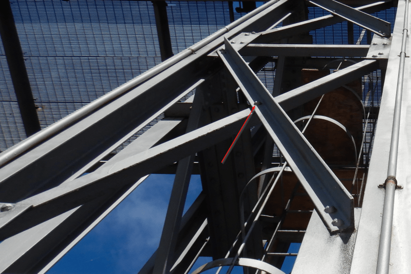
What is the use of a middle rivet in a X bracing? Is it used to reduce the K*L/r ratio? I am asking this because the K*L/r ratio of this bracing is too high (255) if I don't consider the rivet in the middle. I am evaluating this existing structure. It would be odd that the designers at the time (year 1920) would have designed a structure with a K*L/r ratio over 200.
2021-10-26_10_23_49-Window_n8pa4r.png


However, I don't see how the middle rivet can really help to support laterally the bracing in compression against buckling perpendicular to the plane of the bracings in X.
 
Replies continue below

Recommended for you

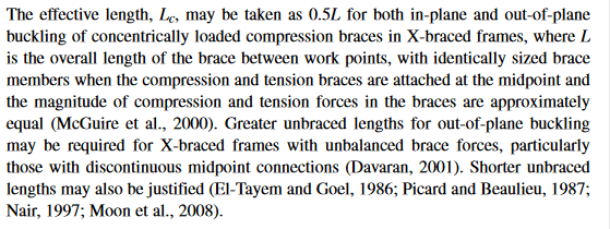
If you are concerned with bracing the compression diagonal with the tension diagonal, AISC added the following to the Commentary of Appendix 7 in the 2016 Spec. (p. 16.1-569 available for free: PDF page 627). One of the references is that which KootK provided, but there are several others provided as well as some acceptable conditions for a 0.5 value.


aisc_nc1q7l_ghhfqb.png
 
Transmissiontowers, how do you treat the total bracing capacity if the situation is such that the loads in the compression and tension braces are equal? The capacity of the compression brace will be less than the capacity of the tension brace due to bucking. Do you add the compression capacity to the full tension capacity, or do you limit the load in the tension brace to the capacity of the compression brace?
 
steveh49;

I guess I'm not familiar with the term "total bracing capacity". In T-Line towers, each of the diagonal bracing's capacities are given in ASCE 10 for tension, compression, bolt shear, and bolt bearing. The actual load is compared to the limiting capacity. Let's assume the diagonals have 10k in ten and comp actual load. In this case the tension brace has more than 20% of the 10k load in the compression brace and you can count on the center bolt for out of plane support and Lz is 0.5L when you compute the compression allowable.

If the tension diagonal has less than 20% of the comp diag load (in my example 2k) then the Lz is 1.0L. I have seen some people use 75% of L and count the center bolt as a partial brace, no matter how small the tension load is.

On the topic of braces slapping, in T-Line towers we add a plastic or metal "ring fill" that is the same thickness as the end connection plate at the intersection of the braces to keep the bracing straight. You definitely do not just tighten the center bolt to bring the angle legs together and bow the members.

HTH


_____________________________________
I have been called "A storehouse of worthless information" many times.
 
i remember reading once that it is unclear whether if you use a configuration like that as tension only
and in stress reversal the before compression member that buckles has to now take tension

personally ive seen disputes where similar steel structures were to be modified and engineers disputing
whether to retrofit the bracing to satisfy this.

fem will more than likely tell you your member has failed due to compression and you end up sizing accordingly

this will also reduce your tension load if you want to consider tension only

i believe code does not support using stiff members as tension only (correct me if im wrong)
 
Ttansmissiontowers,

In the first post, the Le/r ratio was given as 127.5 assuming Le is taken as half the length of the angle member. The compression capacity would then be about 40% of the yield strength (dependent on steel grade and governing code). If you limit the load in the tension brace to the same value, the total capacity of the bracing system is 80% of the capacity of just the tension brace. Or do you take 40% + 100%?

I think wrxsti's comment/question is along the same lines.
 
I just reviewed ASCE 10, it states the following:
"If the member in tension has a force of not less than 20% of the force in the compression member, the crossover point provides support resisting out-of-plane buckling."

As far as I can find this is only stated in example calculations - it is not mentioned in the body of the standard.

 
Personally, I think it's best to treat the effective length as the actual length of each member and ignore the midpoint.
Moreover, I think it's a bad idea to reduce the braced length.

Furthermore, X-braces are often designed as tension-only, and compressive forces are neglected in the brace. That is, in tension members, the effective length is L/r. The K factor only applies to compression members (which again, are neglected).

Other reasons why I wouldn't use a lower K-factor in a brace:

1) A truth: most buildings could use more bracing.

2) An analogy: I don't consider the strength/brace contributions of things such as handrail, pipes, and etc. because I don't want to rely on those elements to hold up a building. I tend to view the bolt at a brace intersection the same way. Do those things contribute strength? Probably. Is it worth risking health and safety? Seems a penny wise and a pound foolish to me.

3) A conjecture: I think that the effective length of a bracing member is likely proportional to the total length of individual brace members. 2' brace members tied together in the middle are going to distribute force pretty evenly between the 4 connection points. I'm not sure if the same logic applies to a 1000' long bracing member - it seems like it would act more like a cable at that point, and any out of plane resistance that it might offer would likely be negligible. That's all conjecture, I don't have any numbers to prove it.

4) Practicality: conducting an exhaustive study to determine whether or not you can reduce the is probably going to cost the client a lot more money than it would to just replace the brace with a bigger piece of steel.
 
I can't quibble about the conservative assumption of neglecting the effect of the bolt at the crossing point. But in the worst case, the ultimate capacity will be the factored tension in one brace plus Pcritical of the compression brace.

BA
 
BA if the structure would behave like that
why doesn't FEM software pick that up?


I can't speak for FEM software, but a column which fails by buckling continues to carry Pcritical for as long as it is prevented from collapsing.

BA
 
yea it makes sense that before excessive deformation from buckling the tension side would pickup the force beyond Pcrit
to prevent it

but when you run the fem it doesnt stop the load at pcrit and redistribute into tension member
i am not sure if its because some software, the analysis is separated from design which would tell you if the member fails

and analysis is more member force etc

but even then stiffness is considered in analysis and deformations generated etc.


wrxsti - you also have to remember that a lot of basic FEM modeling software neglects buckling altogether in the analysis. Some offer it as an option, but it tends to increase the computing power required and time to complete the analysis. In large scale building models, it often isn't practical and is reserved for smaller sections with critical components or for failure analysis. The goal of a whole building model is generally to determine the behavior of a structure that meets code, so buckling is generally precluded. They compare the force in the member with the code limit state equations for buckling, and if it passes then it doesn't buckle and can be used in the elastic analysis. If it fails, you change the size until it passes and then your model can be used in an elastic analysis.
 
CrabbyT said:
Personally, I think it's best to treat the effective length as the actual length of each member and ignore the midpoint.
For most designs I agree. But for some reasons an engineer might want to save costs, especially for repeated structures like transmission towers, or analyse old structures with this sort of design. So the discussion is certainly useful.

wrxsti said:
why doesn't FEM software pick that up?
Not all FEM software includes buckling analysis. Besides who regularly uses Finite Element Modelling to design whole steel structures? That sounds like a painful process. Most structural analysis software that I have used will halt analysis or simply disable the member that buckles. So it won't incorporate the strength/stiffness of the buckled member.

I do use FEM software to design bespoke vessels and other items. But when I'm doing that I'm still only modelling a very small part of the item for buckling. Normally a proper FEM buckling analysis needs small meshing and long computation times.

Nastran that I used would accurately calculate stresses/forces in the compression and tensions members at the selected loads or to the critical loads. However the critical buckling point considered will be higher that the reduced codified Pcrit. So your values are still going to be off. I do not know of any FEM software that will work to the reduced Prcit as opposed to the theoretical eigenvalue buckling point.
 
thanks for the response guys
i found this article... seems to be okish

if anyone interested


and this


also

from
website said:
The result of alternating between tension
yielding and compression buckling of the bracing leads to
deteriorating and pinched hysteretic behavior in
compression cycles, which is the main characteristic of
TOBFs. According to seismic provisions of AISC 341-10
(AISC 2010), the use of tension-only bracing is not
permitted as special concentrically braced frames (SCBF)
and it is only permitted as ordinary concentrically braced
frames (OCBF). In the active seismic areas, using the TOBF
system is not recommended in medium and high-rise
buildings (Filiatrault et al. 1998).
 
wrxsti said:
why doesn't FEM software pick that up?

risa3d has 4 settings for any given member: "both ways" (tension and compression), tension only, compression only, and Euler Buckling. I'm not sure if this is exactly what you're talking about but it will only allow the member designated as "Euler buckling" to attract as much load as the calculated buckling load. I've never used them but that's my understanding of how it works.
 
Status
Not open for further replies.

Part and Inventory Search

Sponsor