Eng-Tips is the largest engineering community on the Internet

Intelligent Work Forums for Engineering Professionals

  • Congratulations waross on being selected by the Tek-Tips community for having the most helpful posts in the forums last week. Way to Go!

Control Config. of two Pump Groups Feeding the same Tank

Status
Not open for further replies.

Jack.C

Industrial
Feb 17, 2023
12
0
0
CH
Dear all,

I have a situation here which has been bothering me for a while and I really hope someone can give me their expertise on it.

Background:
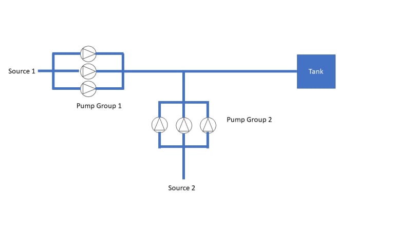
I have two pump groups (let's assume three pumps in parallel each), which deliver up to 1.5 m3/s maximum.
The amount delivered can vary between pump group 1 and pump group 2 (depending on the supply upstream).
In normal operation, however, both pump groups should deliver the maximum flow of 1.5 m3/s.
The main line to the tank is relatively long and pump group 2 does not lead far from pump group 1 into the main line (i.e. they merge somewhere at the beginning of the pipeline).

Below you can find a very simple and basic sketch of the set-up:
Sketch_g1wqrt.jpg


I have thought of 3 scenarios on how I could choose the pump / motor type & control configuration:
[ul]
[li]Scenario 1: Equip the pumps in pump group 1 and 2 with VFD motors. Both flow controlled.[/li]
[li]Scenario 2: One pump group with fixed speed motors and downstream a pressure control valve. The other pump group with flow controlled VFD motors.[/li]
[li]Scenario 3: Both pump groups with fixed speed motors and a one with a downstream pressure control valve and one with a downstream flow control valve?[/ul]

My questions

If both pump groups are equipped with VFD motors: Does one pump group have to be pressure controlled with the other pump group being flow controlled?
Do you see a disadvantage to having one pump group pressure controlled? Is it possible that the flow set point cannot be maintained? Assuming that all pumps in the two groups have similar characteristics?[/li]
What would make the most sense in your opinion, smartes control configuration, or be technically easy to implement. For what reason?

I'm thanking all of you in advance for your valuable inputs.

Kindest regards,
Jack
 
Replies continue below

Recommended for you

All you need is a way to get PS2 pumps to deliver into the pipeline by matching the pressure created by PS1 pumps - friction loss to the injection point.

You can do that as you have surmised by any kind of control of the pump stations; VFD or Fixed speed or a combination of both.

What makes one method, fixed or VFD/VSD, better than the other is ...

Will you have varying flow?
Where will that variation occur?
If flow rates will vary by more than 25% AND
you will spend a lot of time pumping those lower flow rates, VFD/VSD might work, but you also need to know if it can work. The VFD pumps need to create enough head at their lower speed to deliver into the system at either or both points. VFD Head decreases by speed squared. At 75% speed, discharge Head drops to almost half, 56% of 100%speed. If your pipeline only needs 56% of head to move 50% of that lower flow rate, VFD could be suitable. If your pipeline needs more than the VFD Head available, you must use fixed speed with a control valve.

If you have predicted a lot of time at <80% flow at either PS1 or PS2, or both, that's the place(s) to try VFD. If either pump station is mostly constant flow, always above 80%, do not put VFD there, use fixed.

Flow or pressure control? Either will work. Just use the same for both stations. A mix of flow and pressure control valves just creates an additional logic problem for the control system and operators. The most intuitive for a pump is pressure control, but humans like to work with their flow rates.


--Einstein gave the same test to students every year. When asked why he would do something like that, "Because the answers had changed."
 
As George says, depending on what you really want to do, level control may be better than either flow or pressure control. And any control variable can be rigged to either operate operate on/off fixed speed, or your VFD. Do you prefer, or can you have on/off control, or must you slowly, slowly reduce flow as you reach the tank top?

--Einstein gave the same test to students every year. When asked why he would do something like that, "Because the answers had changed."
 
I'm with the others here - first you need to decide / determine what is controlling your two pump sets when they are not at max flow.

Unless you have no restriction on your inlet flow the idea of a pressure controlled doesn't work for me.

But this is essentially no different to a two pump parallel pump set up.

A lot depends on the relative pump curves and system curves in terms of how the two sets will react.

The pump sets need to be very similar, but operating in a steeper part of the curve.

It looks to me like they should both operate on flow control, but if you're normally operating flat out, then a VFD isn't required and will just add CAPEX and OPEX costs for little benefit.

If you can post a pump curve and system curve maybe one scheme will jump out and also what is controlling the flow if its not 1.5m3/sec. That's a pretty big flow rate though - 1.5*3600 = 5,400 m3/hr ...

Remember - More details = better answers
Also: If you get a response it's polite to respond to it.
 
Dear all,
Thanks a lot for your feedback. I really appreciate that.

@1503-44: I'm not sure yet if we are expecting a varying flow rate or not (>80% or < 80% of maximum flow for a longer time period) -> will be clarified. However, I've learned that at both stations we have a buffer tank of around 2 x daily flow volume. In this regard, I strongly assume that we normally operate > 80% of MDF). Furthermore, I will definitely consider your input not to have different control philosophies (flow & pressure controlled) for the two pumping stations.

@ georgeverghese: There is no level control foreseen. The only control parameter we will have from the upstream tank will be an interlock for the pumps (level switch high). In this regard, the only requirement here is to supply enough head to fill the tanks (obviously :) ). Normally they should be filled 80%. By pressure control I meant that one pumping station is is able to generate the same pressure as the other one - when e.g. the flow supplied by one pumping station must be doubled as the flow supplied from the other pumping station.

@LittleInch: As stated above, I assume that normally we are supplying with a fixed setpoint. Only in unusual situations, the setpoint is lowered. It could be the case that PS1 is running at the normal setpoint whereas PS2 is running at a lowered setpoint (or vice-versa). However, I don't assume this to happen often (I'll clarify this). For the moment I don't have any pump curves available. But what I'm going to do next is to simulate a few scenarios at varying flow to obtain the system characteristics. In the end (in my optionin) it is important that the pumps of the two station have the same characteristics - preferably to be supplied by the same manufacturer. Regarding the flow rate: the MDF for each pumping station is even higher (2.3 m3/s) => in the end we are talking about 4.6 m3/s for the pipeline downstream of the itnerface point. The amount of pumps required at each pumping station is still under evaluation.

Wishing you all a nice day,
Jack
 
Hi Pierre!

Thanks for this reminder. Check valves at discharge side are foreseen for each pump. I don't see the need to have an additional one at the pumping station outlets. Do you agree on that?

Best regards,
Jack
 
I think I would just go for fixed speed pumps and two control valves controlled on flow.

Beware that you will get the same issue with your three pumps in parallel where no pump is exactly identical. hence why you duty point needs to be on a more steeply sloping part of the curve to avoid one pump taking > 505 or 33% of the flow (2 pumps or 3 pumps running.

Remember - More details = better answers
Also: If you get a response it's polite to respond to it.
 
Control of pressure or flow yields the same hydraulic result.

TYPE OF CONTROL
If flow controlled, any flow rate "Q"an operator dials in requires the valve to be at a certain %Open needed to get that flow rate in the system. That flow rate "Q" requires the ststem pressure at the valve to be "P". Conversely if pressure controlled, the operator dials in P and the valve goes to the same %Open to make the system flow Q. The only difference is how the design engineer thinks is the best way to keep a particular system controlled and why. If there is a pressure limitation somewhere, control of pressure is logical. If you want to make flow rates, why buy the P to Q logic chip. Just make sure you design the pipe for the maximum pressure needed to make it flow what you want within the pressures it can handle.

CONTROL LOGIC
If you want to make deliveries at certain flow rates, flow control is logical. If you want to keep a tank full, level control is logical. The valve does not care one bit which one you use. The valve goes to a certain %Open to do whatever the PID told it to do. If the PID has a flow to position logic, the operator can dial in flow. If the PID has pressure to position logic, the operator can dial in P. If the PID has level to position logic, the operator can dial in level.

As such, it is not normally convenient to have flow control at one PS and Pressure at another, if both stations are delivering flow.
On the other hand, if station 1 is delivering all flow while station 2 is only maintaining the pressure needed to deliver PS1's flow to the tank, a flow and pressure control mixture would be appropriate. Flow control at PS1 and pressure control at PS2 would do that job nicely. The control system you build should suit the logic according to each PS's design function in the system and the system's purpose.

It would appear, flow control of both stations would be logical, to quote Dr Spock.

PUMPS
You may not be able to use similar pumps without loss of energy efficiency. That may depend on how you will want to operate. If both stations are running, or have different flow rates, or head requirements, they may have vastly different system curves. If flows from each station are similar and they operate separately, one on, one off, the system curves may be similar enough to get away with using similar pumps. The distances between PS and to the tank will also all affect that possibility.

TANKS
If you can get them sized large enough to meet needs between minimum and maximum demands, you can pump at the average flow rate all the time. Fixed speed, no control valves. Pipeline flow capacity would not need any deviation at all. Usually one must find a balance between tank cost and flow controll capacity cost and system complexity. Tanks get expensive quickly, but if variations are not extreme, reasonably sized tanks are possible and average flow rates are perfect.
If you handle flow rate variance with control valves, number of pumps in parallel, tanks, vfd, or a combination is a question of optimization costs. Sounds perfect for a genetic optimization algorithm.

--Einstein gave the same test to students every year. When asked why he would do something like that, "Because the answers had changed."
 
Hi all

@LittleInch: Noted. Thanks for your advice! I'll definitely consider that in my proposal.

@1503-44: Agree with you. I think it's a matter of experience. Some operators are more convenient by setting the Q setpoint and some with P setpoint. The pipes will be designed accordingly by defining a proper design pressure.
- Regarding the P-Control Logic: I'm planning to have a top inlet to the tank (with a downcomer). Therefore, I assume a flow setpoint is more suitable in this regard. What you're describing makes lot of sense to me. A switchover in the DCS from Q to P setpoint is definitely something we can implement. This a long way to go :)
- Regarding Pumps: Thanks for this input. Something I should check in detail in the model to - also in terms of energy efficiency. What I don't assume is that the will have different head requirements. But I cannot confirm this at current stage. Another point which I'm still working on is the need of Booster Pumps and the number of pumps in parallel.
Amount of pumps in parallel per station: This is not yet defined (my sketch above is just a rough estimation). Do you have any experience in determine the amount of pumps? Is there a rule of thumb?
Necessity of booster pumps: I'm still not sure what upstream pressure I'm expecting from the buffer tanks to meet the NPSH requirements for the main pumps. Still under clarification.
- Regarding Tanks: Noted. Thanks for your advice. A genetic optimization algorithm sounds interesting to perform - If I only had time for such a study.

 
Station head will probably be different. PS1 operating at X head, PS2 operating at Y head, mainly because the flow that PS2 is adding could dramatically increase the pressure drop per unit length of pipeline and if the distance from PS2 to tank is long, that increases quickly. You might have to use different pipe diameters in each segment PS1-PS22 and PS2 to tank, so that equal head is lost over each pipeline segment's unique lengths.

Number of pumps? Usually boils down to just two issues.

Reason 1 for having more than 1 pump is reliability 2 bilge pumps are a lot better than one when you're far out to sea, or needing cooling water pumps at a nuclear power plant.
Reliability and the possibility of delivering at least something to your consumers when some pumps will not run. If each pump has a 90% reliability, you can efficiently deliver
25 to 33% of max Station flow rate with a reliability of 1- 0.1^3 = 0.999% of the time.
50 to 66% of max Station flow rate with a reliability of 1- 0.1^2 = 0.990% of the time.
75 to 100% of max Station flow rate with a reliability of 1- 0.1^1 = 0.90% of the time.
If you need 100% max flow, all the time, add additional pumps, or a standby pump to the 3.
Of course there is a footprint size and piping, electrical and maintenance cost penalty for that high reliability, but being able to deliver something might also be extremely valuable. Depends on safety, criticality of mission, lost revenue cost and... loss of face with your customers. If your delivery contract has high penalty costs of one sort or another, you want high reliability.


Reason 2,
you need variable Station flow capacity at a constantly high head in a parallel pump arrangement, or increasing heads linearly proportional to flow rate in a series pump installation.

The right number of parallel fixed speed pumps all operating between 70% and 100% of BEP flow can be used to replace a single pump with VFD, in fact even better. For example try 3 parralel fixed speeds efficiently operating with control valve(s) by selecting BEP flow for each pump at 1/3 Max Station flow.
Variable Station flow can then be accomplished efficiently within 3 bands using fixed speed pumps..
Band 1, (0.75 to 1.00) x BEP Flow x 1 pump. Min at 25% to Max of 33% Station max flow
Band 2. (0.75 to 1.00) x BEP Flow x 2 pumps. Min 50% to 66% of Station max flow.
Band 3. (0.75 to 1.00) x BEP Flow x 3 pumps Min 75% to 100% of max Station flow.
And any flow rate you want to run over 50% Station max flow will not be horribly inefficient.
And, even better, all those low flow rates are possible as there is no low vfd head penalty due to low head output at lower rpms. Vfd eliminated. Hi reliability.

You could do something similar with vfds too, but head required should be proportional to vfd speed squared.


--Einstein gave the same test to students every year. When asked why he would do something like that, "Because the answers had changed."
 
Am not sure if you have told us all that needs to said, but at the moment, I dont see any need for automated controls. Why not install a butterfly at the common discharge of each set of pumps, and adjust the valve setting so you get equal flows from each set ? Why VFD, pressure control, flow control ?
 
Hi,
You may also consider having two separate lines to supply your tank, manual valves to manage the flow and may be an interlock LSL (float or equivalent) to restart the pumps.
My 2 cents
Pierre
 
Yes. Believe it or not, 21 of us "pipeline start-up" engineers ran a 5 pump station, 800 km long production plant, pipeline and a marine terminal for a year with only mobile radios, no SCADA system, manual pump starting and speed control, manual control valve setting adjustment, including using glass pressure and tank level gages, and tire jacks to position the valves when the actuator's N2 supply ran out while holding backpressure on a 1000m downslope in the Andes foothills through an old river crissing while they were still installing the new one, all while the querillas attacked the pipeline twice a week. We tried to use the microwave comms, but they kept blowing up the towers, All without even a TI-45. Even the air conditioners didn't work 100F, 100% humidity. Now that was a real control system. All this new stuff is just fancy gold plating. [hairpull2]

--Einstein gave the same test to students every year. When asked why he would do something like that, "Because the answers had changed."
 
Status
Not open for further replies.
Back
Top