Continue to Site

Eng-Tips is the largest engineering community on the Internet

Intelligent Work Forums for Engineering Professionals

  • Congratulations MintJulep on being selected by the Eng-Tips community for having the most helpful posts in the forums last week. Way to Go!

Designing an atmospheric storage tank recirculation system - pump control strategies? 2

Status
Not open for further replies.

HaxNobody

Chemical
Aug 6, 2024
19
I'm working on a 10,000 gallon storage tank for reverse osmosis purified water that needs to be recirculated through a UV sanitizing reactor. I would like help on the correct strategy for controlling the pumps in this loop. The loop design is as follows:

I have two 10HP centrifugal pumps in parallel, each with its own check valve on the discharge. They can achieve up to 62 PSI of head pressure at zero flow. These pumps feed directly to the UV reactor.
After the UV reactor, I have a 240 GPM flow restrictor valve that is intended to prevent the UV system from exceeding its design flow rate. This restrictor valve could have 15-20 PSI drop when running at its full flow rate.
The line then goes out to the process loop, where various equipment taps in to draw from the loop to feed mix tanks and other processes. The loop pressure should be around 30 PSI when recirculating under "idle" conditions with no draw off the loop.
When the loop returns, it goes to a set of 1 micron absolute rated sediment filters.
After the filters, the loop then goes to a backpressure regulating valve that is set to maintain around 170 GPM of tank return flow when the loop is idle, to achieve 1 tank turnover per hour.
The backpressure regulating valve is set to 10 PSI, and it will maintain around 30 PSI at design flow. If the loop pressure drops because other processes are drawing from it, the backpressure valve will close and create a "dead leg" at the end - to prevent this, the backpressure valve also has a 10 GPM flow restrictor in parallel to ensure some amount of minimum flow is still achieved.

Both pumps are on their own VFDs, and I originally intended to control their speed based on a pressure sensor located just before the backpressure regulating valve at the end of the loop. However, I have identified a problem: If the loop pressure is too low because it is being drawn down by process equipment, this strategy would cause the pumps to keep running faster and faster, even though the 240 GPM flow restrictor is going to prevent them from performing additional work. So I need to figure out how to "reset" the pump speed based on flow across the UV reactor. I'm not sure whether I should try and detect actual flow, or if I should try and put a pressure sensor on the UV reactor and try to calculate the differential to estimate flow rate.

There may be other pitfalls that I have not yet identified that you guys might know about. Looking forward to any insights on this - thanks!
 
Replies continue below

Recommended for you

Hi,
You mentioned cosmetic product, this means product subject to regulation. Right now, I'm very worried about the quality of your water and associated treatments. Be extremely cautious if you need to follow GMP.
Good luck anyway.
Pierre
 
pierreick said:
You mentioned cosmetic product, this means product subject to regulation. Right now, I'm very worried about the quality of your water and associated treatments. Be extremely cautious if you need to follow GMP.

Interestingly enough, in the US it's kind of the opposite. Although we obviously do try to make a good product to high standards, there is essentially zero regulation on cosmetic products as long as we make no claims on the label, which I'm sure is quite different to most of the rest of the world. As we transition towards some newer products that do make claims, these begin to fall under the purview of the EPA, and we will being auditing the entire process to ensure compliance. It's sort of a "wild west" out here.
 
Haxnobody,

I think we're in danger of over complicating this now so hope you have enough information to make your particular system work as you need it to.

Your original design was a bit marginal to me as to whether it would supply your users with what they need, but hope you have enough now to design something better.

I do see what you mean about AMT pumps - they don't kill themselves providing you with any serious technical information do they?

Fisher make proper control valves so not surprised at their cost....

If you don't need high accuracy, I still think a butterfly valve with a stepper motor should give you good service and you can get them in PP.

Anyway, please let us know what you've decided to do after ruminating on this a little bit....

Remember - More details = better answers
Also: If you get a response it's polite to respond to it.
 
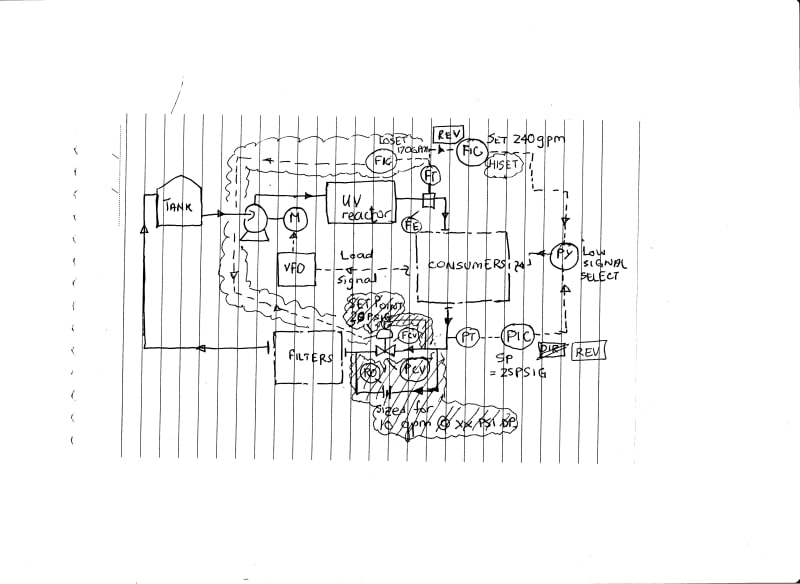
Forgot the bit about the 170gpm min flow requirement. Given the feedback you've got so far from Flomatics and Fisher, here is a revised scheme that will keep this min flow of 170gpm through the tank and filters and UV reactor. Deleted bits from previous scheme are shown shaded out.
Backpressure PCV replaced with a regular control valve to act as min flow control valve (sizing case flow 170gpm with pressure upstream of 30psig, some 10psig(?) downstream, with valve at 70-80% open). No need for CDX10 either. Both hiset and lo set FICs' run off signal from the same FE/ FT. By the way, presume you have some kind of flow restriction device at each consumer to prevent overdraw on supply / supply pressure collapse - perhaps a Flomatics CDX device may do on each user.

E-Tips2024Aug13pumpcontrolsB_aoiquc.jpg


PS :Error in my sketch/ narrative here : Since you dont want a dead leg at the filters and return line either when flow through UV reactor is more than 170gpm, keep that CDX10 on the bypass around the FCV.
 
LittleInch said:
Anyway, please let us know what you've decided to do after ruminating on this a little bit....

I'm going with George's design because it makes complete sense. It's similar to what I started with but with all the missing blanks filled in.

georgeverghese said:
Forgot the bit about the 170gpm min flow requirement. Given the feedback you've got so far from Flomatics and Fisher, here is a revised scheme that will keep this min flow of 170gpm through the tank and filters and UV reactor. Deleted bits from previous scheme are shown shaded out.
Backpressure PCV replaced with a regular control valve to act as min flow control valve (sizing case flow 170gpm with pressure upstream of 30psig, some 10psig(?) downstream, with valve at 70-80% open). No need for CDX10 either. Both hiset and lo set FICs' run off signal from the same FE/ FT. By the way, presume you have some kind of flow restriction device at each consumer to prevent overdraw on supply / supply pressure collapse - perhaps a Flomatics CDX device may do on each user.

PS :Error in my sketch/ narrative here : Since you dont want a dead leg at the filters and return line either when flow through UV reactor is more than 170gpm, keep that CDX10 on the bypass around the FCV.

I thank you very much for your help and drawing. To limit tank fill rate I had been relying on pipe sizing, but using a CDX device on those is a good idea and makes the loop more predictable to operate. I'm going to integrate these changes into my drawings and get going on building this system out. [thanks2]
 
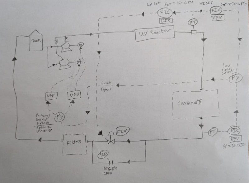
I went ahead and re-drew the diagram to make sure I understood it and to incorporate errata, as well as adding the dual pump setup. Hopefully this seems correct:

PXL_20240814_175026224_svzrwn.jpg
 
Okay. You can run with this now.
Some minor "grammatical" improvements:
a) the weekly switchover selector is usually marked as HS - hand signal for local manipulation
b) the CDX 10 on FCV bypass is not a regular restriction orifice, and I dont know what the symbol and label for this is - maybe someone reading this with more instrumentation knowledge on ISA symbology can help
c) the signal going to the FCV is usually shown going to the actuator of the valve, not the body of the valve. BTW, what type of control valve will you be going for here ? @ LI suggested an all electric stepper motor actuated one, if that turns out to be cheaper than a pneumatic control valve with I/P convertor and feedback positioner ?
 
georgeverghese said:
Okay. You can run with this now.
Some minor "grammatical" improvements:
a) the weekly switchover selector is usually marked as HS - hand signal for local manipulation
b) the CDX 10 on FCV bypass is not a regular restriction orifice, and I dont know what the symbol and label for this is - maybe someone reading this with more instrumentation knowledge on ISA symbology can help
c) the signal going to the FCV is usually shown going to the actuator of the valve, not the body of the valve. BTW, what type of control valve will you be going for here ? @ LI suggested an all electric stepper motor actuated one, if that turns out to be cheaper than a pneumatic control valve with I/P convertor and feedback positioner ?

a) Noted. I'm going to try and make that automatic.
b) Noted.
c) That makes sense, I didn't even think about that. I'm going with an electrically actuated v-ball with position feedback because that's my area of comfort. I'm sure the pneumatic stuff would work great, I just don't want to run air all the way over to this area.
 
Looking good.

I'm not sure though about what signal you're sending to the FCV before the filters?

In an earlier post you said basically that you have 240 GPM from the UV filters, but then consumers of up to 200 GPM. So this would only leave ~ 40 gpm to go through the filters.

Maybe your PT set at 35 psi will then kick in to restrict the flow through the filters for the time period you're filling?
Otherwise if you try to maintain 170 gpm at all times through the filters you will starve the consumers.

Probably needs an operating and control description to go with this.

But definitely a lot better than the initial design.

Remember - More details = better answers
Also: If you get a response it's polite to respond to it.
 
LittleInch said:
Maybe your PT set at 35 psi will then kick in to restrict the flow through the filters for the time period you're filling?

My understanding and interpretation of how it works is as follows:

The backpressure valve closes as flow rate increases above 170 GPM, eventually shutting off completely to prevent starving consumers. When the flow rate is at or under 170 GPM, the backpressure valve is wide open.
The VFD increases the pump speed when the flow rate drops below 240 GPM, or the pressure signal drops below 35 PSI. The low signal selector chooses the lesser of the two values.

Therefore, the following scenarios can occur:

Scenario 1: Idle loop (no consumers) with clean filters:
Loop starts at zero flow and zero pressure. When the VFD is enabled, both the FIC (REV) and PIC (REV) are sending a request for maximum pump speed.
The backpressure valve is wide open because FIC (DIR) detects no flow.
As the flow increases, the pressure builds in the loop. Since we have less than 35 PSI total drop from the loop head loss and filters being clean, the loop will achieve 170 GPM flow prior to either the PIC (REV) or FIC (REV) backing off the VFD signal.
The flow rate will exceed 170 GPM, causing the backpressure valve to start to close from the FIC (DIR) signal.
As the backpressure valve closes, the pressure will begin to rise, and PIC (REV) will start to back off. This will cause the VFD speed request to drop because the lower of the two signals is chosen by the low signal selector PY.
The VFD speed will slow down until PIC (REV) setpoint is reached, and will maintain its speed based on PIC (REV).
FIC (REV) setpoint will never be reached until consumers cause some demand.

Scenario 2: Idle loop flow with dirty filters:
Basically the same as scenario 1, except that FIC (DIR) never actuates the backpressure valve due to the filter pressure drop.
VFD runs off of PIC (REV) setpoint.
FIC (REV) setpoint is still not reached because no consumers are using any flow.

Scenario 3: One consumer starts using approximately 120 GPM from the loop:
Assuming the loop was previously idle and is not starting from zero.
The loop pressure immediately drops due to the additional flow being taken. This causes PIC (REV) to speed up the VFD.
Loop flow rate increases, so FIC (DIR) begins closing the backpressure valve to maintain loop pressure.
However, FIC (REV) approaches setpoint because of the additional flow. As FIC (REV) starts to back off, its value becomes less than the value of PIC (REV).
The low signal selector PY switches control from PIC (REV) over to FIC (REV) which causes the VFD to back off to prevent overrunning the UV reactor.
The loop will eventually stabilize at a flow rate through the filters of around 120 GPM.
The pressure at the backpressure valve will be less than setpoint, perhaps around 25 PSI or so.

Scenario 4: Two consumers begin to use the full 240 GPM loop flow rate:
Same as scenario 3, except that FIC (DIR) causes the backpressure valve to close completely to try and maintain loop pressure.
PIC (REV) will never be satisfied and will continue to output a high signal, which is ignored because of the low signal selector PY.
FIC (REV) will be solely responsible for VFD speed control according to actual flow rate through the UV reactor.
Since the backpressure valve is closed, any remaining loop pressure will squeak through the CDX10 flow restrictor valve to try and keep things moving back to tank.
 
Ok I can see that working.

the only one is this bit from scenario 3
"Loop flow rate increases, so FIC (DIR) begins closing the backpressure valve to maintain loop pressure." I think is incorrect as the back pressure valve is only being controlled on flow.

What I think it does is this
Loop flow rate increases, so FIC (DIR) begins closing the backpressure valve to try to maintain 170 gpm. Loop pressure is controlled by the VFD and maintains 35 psig by increasing speed.

The loop will stabilise, but you might need to play with the reaction times to stop these two things hunting.
The back pressure valve will continue to close if the flow is higher than 170 until it becomes fully closed if you are filling two tanks say.
Only filling one it will close the vale until you hit 170 out of the UV filter. Pressure will look after itself on the VFD.

Scenario 4, again the back pressure valve closes because it is trying to maintain 170 gpm, not pressure.


Remember - More details = better answers
Also: If you get a response it's polite to respond to it.
 
Right, it's controlled by flow, but the only reason it exists is to create backpressure to assist loop consumers.
 
@Hax, I see some anomalies in your controls narrative:

General comments:
a)"The VFD increases the pump speed when the flow rate drops below 240 GPM, or the pressure signal drops below 35 PSI."
It should read as " The VFD decreases pump speed when flow rises beyond 240gpm, or when the pressure signal rises beyond 35psi"
b) The FCV is no longer a backpressure valve, it is a min flow control valve. Backpressure control is now maintained by the PIC set at 35psig
c) The loset FIC set at 170gpm, which now operates an all electric stepper motor actuated control valve, ought to be a REV acting controller - pls revise, unless you see some reason why this FIC should be a direct controller.
d) Since both FICs' are now REV acting, for the sake of these critical control narratives, maybe better to assign tag nos to each.

e)Scenario 1:
e1) " The flow rate will exceed 170 GPM, causing the backpressure valve to start to close from the FIC (DIR) signal".
Should read as: "If the flowrate exceeds 170gpm, ....

f) Scenario 2: Assuming "idle" loop flow means zero flow,
f1)When loop flow is transiently zero, the CDX10 will allow only 10gpm to flow through. The loset 170gpm FIC then will act to open the FIC to maintain loop flow at 170gpm. Loop PIC output will rise and act on VFD to raise pump speed to reach setpoint pressure. At this time, the hiset 240gpm FIC output is at saturation (ie 100% output), so the PY will select and forward the PIC output to pump VFD

g)Scenario 3:
g1) Since consumer demand is only 120gpm, the 240gpm reverse acting FIC will remain at 100% output (total flow is 120+10=130gpm) - the low select PY will not select this FIC output in this scenario - pls revise this entire scenario 3 narrative. The pump will run only on the loop PIC output, which will initially rise, and then stabilise.

h)Scenario 4:
Apply general section corrections only. Otherwise, description is correct.


George,

I get a bit confused by direct or reverse acting, but for me the valve at the end point simply has a set point of 170 gpm. The controller is opening and closing the valve trying to maintain this set point. So >170, valve position to close more, lower than 170 valve position to open more.

Similarly the pressure controller has a setpoint of 35 psi. P <35, pump speed sup, pressure > 35 pump slows down. This time though pressure controller is in control unless flow >240 when pump speed slows down or doesn't increase more due ot the low select block.

Hence when flow exceed 170, the valve starts to close, the pressure rise upstream until its all steady again.

Flow goes lower than 170 the valve opens, the pressure falls and hence the pump picks up speed.

So when someone takes water, the flow will increase and the pressure falls. The end valve starts to close which raise pressure and allows flow to go to the users. If the flow to the users increases, the total flow in will be > 170 and the valve will continue to close until if there is enough demand then all flow minus 10gpm is going to users. Pressure is maintained by the PIC and pump speed unless the flow is > 240 when it is forced lower by the high flow setpoint.

I think "Idle" means no users, but continued flow through the filters and tank??

So I think the logic is sound, but controlling two parameters - flow and pressure - using two different means has the potential to create flow disturbance, hence one or the other needs to react much slower than the other - flow probably being the best one.

Remember - More details = better answers
Also: If you get a response it's polite to respond to it.
 
This is what a direct acting controller does:
If controlled parameter is higher than setpoint, deviation from SP is POSITIVE, controller output INCREASES
If controlled parameter is less than setpoint, deviation from SP is NEGATIVE, controller output DECREASES
For a reverse acting controller:
If controlled parameter is higher than setpoint, deviation from SP is POSITIVE, controller output DECREASES
If controlled parameter is less than setpoint, deviation from SP is NEGATIVE, controller output INCREASES

Sometimes, the final signal to the controlled device may need to be reversed to suit the failure mode of the device, for example if the valve is a pneumatic fail open device.
In this case with a stepper motor actuated control valve, the valve is fail in last position, but am assuming that increasing feed signal is translated into increased opening of the valve.

After all this deliberation, what we have now is a standard run of the mill control scheme for pump operation, with min flow being achieved by flow control, the only peculiarity here being that the FCV is at the end of the loop, and not right after the pump. Tuning of these controllers shouldnt pose any problems here with this simple control scheme.

At the risk of saying the obvious, we also need a ramp up rate limit filter on the PIC output for startup - we dont want the pump to jump start up to high speed straight off the bat (reverse acting PIC will demand the pump go to high speed since loop pressure is now zero - there is no demand, but the FCV is wide open). There are a few wsys to enable slow ramp up to operating speed on startup:
a) Manual method - no ramp up rate limiter
Operator selects Manual mode on PIC and sets output to zero. Then operator starts the pump. Operator slowly increases PIC output on manual mode till SP is reached, then operator switches PIC back to Auto mode.
b)Automatic mode - with ramp up rate limiter
Ramp up rate limiter is activated automatically every time the pump shuts down. When operator starts the pump, the ramp up rate limiter produces an output signal to the PY that rises at X milli Amps / sec, where X is predetermined by engineer. When ramp up rate limiter output signal is within say +/- 2% of the incoming signal from PIC, the ramp up rate limiter is deactivated, and PIC output goes direct to PY. ISA symbology for ramp rate filter will be PY also - add a qualifying descriptor next to the tag label.

@Hax can work out X to suit this application, once the max normal operating rpm of the pump is known. We only need this ramp rate filter on the PIC output, since it operates a rotating machine with limitations on startup current etc. No need for ramp rate limits going to FCV for startup or shutdown.


Status
Not open for further replies.

Part and Inventory Search

Sponsor