Continue to Site

Eng-Tips is the largest engineering community on the Internet

Intelligent Work Forums for Engineering Professionals

  • Congratulations KootK on being selected by the Eng-Tips community for having the most helpful posts in the forums last week. Way to Go!

Help with recirculating pump above tank level 1

tonbaldin

Chemical
Aug 30, 2024
6
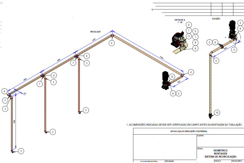
Captura_de_tela_2024-08-30_172917_jl8wdb.png

Hi all!

I need help with commissioning this pump. The design engineer is not around anymore and now I'm responsible.
The idea is to use the centrifugal pump to recirculate and agitate the liquid in the tank.
The piping has an internal diameter of 90 mm. I've already made some calculations for the headloss and maximum suction lift accordint to manufacturer's operating manual and concluded that I had to reduce the pump speed, because the headloss was too high. Even with 1750 rpm the pump can't lift the liquid and recirculate.
I'm considering to increase the pipe's ID to 130 mm so maybe I can operate the pump at full speed.

Any thoughts or ideas that I should try before replacing the piping?
 
Replies continue below

Recommended for you

Increasing the inlet / suction line will do zero for your issue IMHO.

"We've decided to increase the suction pipe ID to 130 mm. I believe this will solve my low flowrate issue." Can you explain your thinking here?

10m of pipe isn't going to generate any sort of head loss at these sorts of velocities so making it bigger will not impact the operation.

Your issue, which is not being answered is what is either the required flow rate or what flowrate are you experiencing when it does actually work?

The higher the flow once you get past about 100m3/hr runs the pump into some very high NPHR figures indicating a lot of cavitation and loss of inlet flow / prime, never mind damage to the pump. It could be a host of other issues, but if you don't control flow you won't be able to address these issues.

Remember - More details = better answers
Also: If you get a response it's polite to respond to it.
 
Many thanks for all the answers.

Measured flowrate?
Maybe it's an option. I'll consider.

The more info you disclosed the more this system seems like there is no engineering behind that.
You're right. I inherited this problem as soon as I was hired.

(2) significant flow restriction at suction (flow orifice)
I don't have a physical one. Maybe you're referring to a fitting or the check valve that plays the same function.

(3) no block valve at discharge (filling is empede)
I do have one.

I suppose there are more items to extend this combo you are hiding from us.
Not on purpose, believe me... this design is also a mistery for me.

"We've decided to increase the suction pipe ID to 130 mm. I believe this will solve my low flowrate issue." Can you explain your thinking here?
Reduce pipe losses. I also have some fittings. The water velocity is way too high.

Your issue, which is not being answered is what is either the required flow rate or what flowrate are you experiencing when it does actually work?
The client expects a minimum flowrate of 110 m³/h.
 
tonbaldin.

You keep talking about "low flowrate" but without a measurement of the flow rate how do you know? This is a small system so pressure drops are going to be low, despite "high velocities"

I'm still of the opinion that you're running off the end of the curve on the RHS and basically cavitating.

Remember - More details = better answers
Also: If you get a response it's polite to respond to it.
 
tonbaldin said:
(3) no block valve at discharge (filling is empede)
I do have one.
Where?

tolbadin said:
The client expects a minimum flowrate of 110 m³/h.
The key word here is "expects". Why not to calculate the flowrate based of pump curve vs hydraulic profile? This calculation is rather simple and fast. Why are guessings&expectations needed?
 
Your pipe lengths are not legible.

So I assume 100 m total equivalent length.
Pipe flow=110 m3/h
Pipe dia=0.09 m
Calculated velocity=4.8 m/s
Calculated Re=41700
Calculated friction factor f=0.014
Calculated friction drop(Darcy eqn)=f*L/d*v^2/2g=18.29 mwc
Available pump head=3.135 bar=31.96 mwc
So please check your pipe length and decide accordingly.


Engineers, think what we have done to the environment !
 
I have a butterfly valve right after the pump.
I did calculate the flowrate, that's why I've start the pump at 50% capacity at the VFD.

LittleInch, I believe you're right. The system won't produce a high pressure drop, so the visual effect of the fluid leaving the pipe won't be turbulent.
 
ton baldin, I'll ask you once again - how are you measuring flow rate?

I think your issue is that in order to get the suction lift, you need to run the pump at a speed where it is operating off the end of its curve and you're cavitating.

A butterfly valve is better than nothing, but without knowing your flow rate you're never going to get anywhere.

I would start the pump on full speed with the valve about 10% open and then slowly open the valve until you achieve your desired flowrate with it being measured some how - maybe mag flo or a strap on ultrasonic meter or anything really. There are many meters which you can insert on a tee and a flange and give you a decent reading.

e.g. https://www.bellflowsystems.co.uk/insertion-flow-meter-guide.html

You also probably need some sort of variable flow control in the three risers if you want to get equal flow down them all as prob >50% of the flow will simply drop down the first down pipe.
 

Part and Inventory Search

Sponsor