Continue to Site

Eng-Tips is the largest engineering community on the Internet

Intelligent Work Forums for Engineering Professionals

  • Congratulations IFRs on being selected by the Eng-Tips community for having the most helpful posts in the forums last week. Way to Go!

Troubleshooting High Vibrations in API 610 Multistage Pump Operating with Saltwater

Jan 1, 2025
19
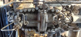
We are experiencing severe vibrations and operational issues with two identical API 610 six-stage centrifugal pumps (6"x6) that were originally designed for crude oil service. We are now using these pumps in different locations to pump saltwater, and the performance has been significantly worse than expected.
Pump Details:
* API 610, 6-stage, 6"x6
* Original design: Crude oil (density 900 kg/m³, temperature 60°C, viscosity 13.2 cSt)
* Design head: 380m
* Design flow: 100 m³/h
* Speed: 2950 RPM
* Impeller: Six vanes
* Diffuser: Six vanes, enclosed type
* Casing: Diffusers separated from upper casing
* Bearings: Dual 7311BECBJ (non-drive end), 6213J (drive end)
* Material: Duplex stainless steel
* Minimum stable flow: 30 m³/h
* NPSHr at rated flow: 2.35 m
Current Operation (Saltwater):
* Fluid: Saltwater (100 g salt per liter)
* Current flow: Reduced to 13 m³/h to control vibrations and amperage
* Symptoms:
* High vibrations, particularly at the non-drive end
* Vibrations felt in the ground around the pump
* Pressure pulsations in suction and discharge (approx. 20%)
* High noise levels with a harmonic rhythm
My colleagues believe the pump's issues stem from it being designed for crude oil rather than saltwater. However, I'm confident that the pump's materials and design are suitable for saltwater. I'm looking for a clear plan of action to address these problems and prevent further damage. Could you provide guidance on where to start and any insights into the potential root causes?
 
Replies continue below

Recommended for you

Can't you simply just tell us the flow and head for the water application, or at least a good estimate.
At the moment it's just a mess of numbers, some very confusing,
ie., in the water duty (?) it says 1 stage, also gives 2 impeller diameters.
 
Can't you simply just tell us the flow and head for the water application, or at least a good estimate.
At the moment it's just a mess of numbers, some very confusing,
ie., in the water duty (?) it says 1 stage, also gives 2 impeller diameters.
I will. Have no access right now.
 
Were these pumps sitting idle for some time before they were switched over to the current brackish water service ? If so, were the seals and bearings cleaned up before moving over to this new service?
 
Well according to that data you are operating below Min inlet pressure(4.5 bar) and minimum flow (5000 bpd).

So not surprising the pump isn't working very well.

Those multi stage units often need quite a high minimum inlet pressure.
 
Well according to that data you are operating below Min inlet pressure(4.5 bar) and minimum flow (5000 bpd).

So not surprising the pump isn't working very well.

Those multi stage units often need quite a high minimum inlet pressure.
Over the coming days, I plan to collect additional data.
For reference, there's a similar, but smaller, pump operating alongside. This smaller pump suction at 6 psi and discharge at 100 psi. It handles a flow rate of roughly 9,000 to 11,000 barrels per day (equivalent to 60 to 73 cubic meters per hour) at a temperature of 20°C (or 68°F).
Would adding a bypass line potentially resolve the issues we're seeing with the minimum required pressure and flow?
 
Supply the necessary data regarding flow and head and you might get something back that's useful, thrashing around in the dark looking for fix-ups to solve the problem is wasting yours and everyone else's time.
 
Supply the necessary data regarding flow and head and you might get something back that's useful, thrashing around in the dark looking for fix-ups to solve the problem is wasting yours and everyone else's time.
The pump is operating under the following conditions:
* Suction pressure: 1 bar
* Discharge pressure: 34 bar
* Flow rate: 40 m³/h to 60 m³/h
non-drive end (NDE) bearing overheating and tripped after approximately one hour of operation. This has happened last time, with the previous incident resulting in damage to the NDE bearing, requiring significant effort to disassemble the pump.
Is it possible excessive axial clearance be the problem?
 
Is there a pump hydraulic performance curve available?
At first look I would say the pump is way oversized for the current application, possibly removing 1 impeller might get you to somewhere near the performance you want.

Why haven't you taken this problem up with the pump manufacturer/ supplier?
 
Presume you mean suction pressure is 1barG?
Earlier posts stated pulsations in suction pressure - can you elaborate?

With suction pressure being 1barg in brackish water service, presume sec seal barrier fluid pressure in accumulator is about 2barg ?
 
This pump uses opposed impellers (3 facing each direction) to balance thrust forces. It still has a balance line to reduce the pressure on the non-drive end mechanical seal. It probably uses two volutes to feed the flow into the long crossover channels from the third stage discharge to the fourth stage at the far end. The vibration could be cavitation from running below best efficiency. But this is less likely if the vibration was reduced when the flow was reduced. It is more likely that the vibration is a result of acoustic resonance in those long crossover channels. If I am correct, the dominant frequency should be at vane pass frequency (6 times run speed). In any case, reducing the impeller diameter should improve the situation. This would reduce the best efficiency point which moves the pump flow closer to BEP. This also increases the B-gap, as you noted. A larger gap reduces the pressure pulsations at vane pass frequency. I would recommend only cutting back the impeller vanes while leaving the impeller shrouds at full diameter. If this did not work, you might have to change the vane count on the third stage. Five vanes would be my best guess to solve this. I have had to resort to that solution in a few of our pumps. Accoustic resonance is surprisingly common on pumps of this type. I have seen it on the test stand running on cold water and in the field running on hot oil or hot water.

A thorough analysis of the vibration could easily rule out my theory.
 
Last edited:
Something here just does not make sense to me.

First, your data on post 12 clearly state min inlet presure 4.5 bar, yet NPSHR is very low and you're operating at 1bar.

But mainly the data and the graph above clealry show at your flow rates you should have an outlet pressure of about 41 bar, but you only have 34??

I think you need to take this pump apart and find out if you have something damaged inside or you are taking your discharge pressure from the wrong place.
Mpa istead of Kpa to Bar was my fault .thank you. Here the exact numbers and units from datasheet. I doubt the accuracy of the vendor's use of 'Kpa'.
Screenshot 2025-01-20 153547.png
 
Last edited:
@jj - where would this pressure balance be leading out to the NDE seal ? Outside or inside the casing ?
My guess is this balance line is bunged up with calcium and magnesium salt deposits from this very brackish water, or one or more of the impellers isnt developing the head it should.
Agreed, performance curve posted here doesnt match up with stated current operation of 1barg suction, 34barg discharge at say 50m3/hr ( which converts to a diff head of about 340m)
 
The balance line would be external. It would connect the first stage suction to an annulus between the fourth stage suction and the non -drive end seal. Since this line is only for pressurure balance and not thrust balance, it is probably a very small line.
 
If this balance line plugged off, it would have little or no affect on thrust load. It would only result in increased pressure on the outboard seal, potentially resulting in premature seal failure.
 
The balance line would be external. It would connect the first stage suction to an annulus between the fourth stage suction and the non -drive end seal. Since this line is only for pressurure balance and not thrust balance, it is probably a very small line.
My apologies for the delayed response. To clarify, there is no balance line in this system. The photo shows the entire setup. There is a drain at the bottom, but it is not visible in the image. Is it plan 31 (plan 11 with cyclone)or balance line?
 

Attachments

  • Pump.jpg
    Pump.jpg
    2.8 MB · Views: 7
Last edited:
Mpa istead of Kpa to Bar was my fault .thank you. Here the exact numbers and units from datasheet. I doubt the accuracy of the vendor's use of 'Kpa'.
View attachment 3709

Thanks. This looks like Mpa and not Kpa, but I think whoever wrote this didn't do it in stream order, which Ive seen before.

So e.g. max flow is actually associated with min discharge pressure and the reverse also true.

I think you need to look at each line independently, so min inlet pressure is still quoted as 4.5 barg, not the 1 you have.

But there is still a MASSIVE discrepancy between these numbers and the data you provide and the operating data. If the flow is really 30-40 m3/hr then the discharge pressure must be higher than the 34 barg you are quoting or something is getting confused here.

Or your pump is damaged internally, hence the vibrations. So I think the first thing you need to do is strip it down and have a good look. Or for some reason one side of the pump is blocked or restricted and you're getting non balanced flow. Maybe dirt, wax, a stone, who knows.
Thanks a lot. I've learned from your answers. It's confusing because I'm not an expert yet. There is a disposal tank with a normal water height of around 10 meters (maximum 14 meters) of salty water. Approximately 150 meters of piping with many connections and direction changes, including two gate valves, is in place.
There are two pumps operating in parallel. One has many problems. The other is a different size and from a different manufacturer. It's an 8-stage BB3 pump, and it works well. The suction pressure on the problematic pump is 0.4 bar. I don't know why it's not the same as the suction pressure on the pump that's working properly.
The discharge pressure is 7 bar. The normal flow rate for the good pump, when it's operating alone 24/7, is 11,000 barrels per day (72 cubic meters per hour). When we start the pump that's shaking, the total flow rate from both pumps is only about 16,500 to 17,000 barrels per day (112 cubic meters per hour).
 

Part and Inventory Search

Sponsor