Continue to Site

Eng-Tips is the largest engineering community on the Internet

Intelligent Work Forums for Engineering Professionals

  • Congratulations pierreick on being selected by the Eng-Tips community for having the most helpful posts in the forums last week. Way to Go!

Control Methodology for simaltaneous Level & Flow 2

Status
Not open for further replies.

Iomcube

Chemical
Dec 11, 2015
187
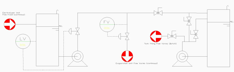
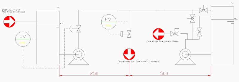
Our electrolyser produce a constant (fixed) flowrate of 10m3/hr 32%NaOH. Part of this goes to evaporation unit (for producing 50% NaOH) & part of this goes to storage tank.

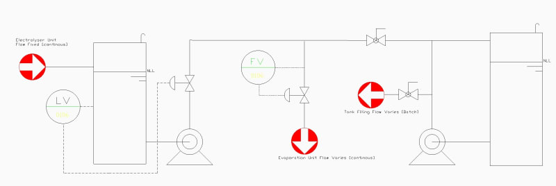
In the illustration I had added what is to be achieved. First level control of first tank & flow control to evaporation. Per my understanding I will go with this process control scheme. Do please share your input

The second storage tank is a large one. Its pump will run sometimes if the sale of 32% caustic is low & thus evaporation at that time will run at a higher capacity i.e it will take flow both from Electrolyser tank pump & storage pump. Both pumps are identical & the line lengths are no more than 700m

download.aspx_z1fh08.jpg
 
Replies continue below

Recommended for you

Tanks are more efficient contributors to a process when their level (you do not have SHL/SLL shown ) can vary between limits, so why does your left tank need to have a constant level? If so, an on/off run of pump could eliminate the level control valve. Does pump run all time. You have not shown pump controls.

What prevents filling the right tank when right pump runs?

--Einstein gave the same test to students every year. When asked why he would do something like that, "Because the answers had changed."
 
@ 1503-44
It's a simplified diagram & I do have skipped pump controls. As indicated on the diagram Electrolyser will continously send 10m3/hr flow so yes first pump will continously run while the 2nd pump will batch run as I had mentioned earlier. Even in the diagram I had mentioned batch & continous keywords
 
It's too simplified. It means we can't understand what is going on.

The second pump will just pump round in a circle back into the tank.

We need volumes as well and why did that first tank exist? Didn't seem to be of any purpose.

Remember - More details = better answers
Also: If you get a response it's polite to respond to it.
 
1. The LV can be moved to the inlet of the NaOH Supply Tank for controlling the inlet flow.
2. Base on the flow control of the Evaporation Unit, the excessive NaOH flow can be routed back to the Supply Tank to maintain the minimum pump flow requirement.
3. The storage tank and batch operation pump at right hand side seem to be redundant and can be deleted.
4. To simplify the operation facility, make the "large" storage tank to be the Supply tank. So, it can satisfy the operation requirement for both low and high NaOH flow requirements for the evaporation operation.
 
@ LittleInch
I will add more details to diagram. For now: The 2nd pump when 'on' will transfer caustic either to evaporation unit or to a sale tanker

@ mk3223
Point 3 & 4: Storage tank is a huge tank which receives 32% NaOH from other sources as well. First tank cannot be eliminated as its the supply / buffer / re-circulation tank for evaporation unit

My main concern:
The LV %valve & FV %valve will work in-situ. Will it create problem for the operational control?
 
It's not appropriate to ask for comments on control systems without providing all details of the process, including what I asked in my questions.

At this rate it will take 499 comments cycles to get nowhere.

--Einstein gave the same test to students every year. When asked why he would do something like that, "Because the answers had changed."
 
@ LittleInch

SmartSelect_20230703_022033_GnaCAD_ayxn8r.jpg


The second pump will just pump round in a circle back into the tank.
Corrected

We need volumes as well and why did that first tank exist? Didn't seem to be of any purpose
The purpose is defined in my previous reply to @ mk3223
For volumes flowrates
From Elz: max 11m3/hr
Pump rating (both): 3.6barg 18m3/hr
1st Tank: 11m3
2nd storage tank: 150m3
Evaporation designed feed flow: 15m3/hr
 
Yes, we can see from your controls that FIC-FCV (to evaporation) wont work when sales storage tank level is not high enough.
Knee jerk suggestion for change would be to
a)Delete the jumper line from sales tank pump that joins the main inlet line to the sales tank
b)Install a new line from this sales tank pump discharge to the evaporation line feed teeing in after the FCV. This line may need to operate on flow control.
c)Relocate the LCV to the inlet of the sales tank.
d)The FIC loop may need a set point reset from the current LIC for cases when level in first tank is low.


Hi,
Suppose the tanks are close to each other, I will connect them at their bottom, I will have a pump to supply the evaporators unit and the batch unit. The second pump should be a spare in place.
You may have a LIA to follow the stock and one LSL to protect the pump(s)and a LSH (option) to cut the supply to the tanks.
At the discharge of the pump(s) after the Tee to supply the batch unit, one FCV to feed the evaporators unit.

My view
Pierre
 
an still only see apart of this but there seems to be some strange numbers here.

If the only net or "normal" flow into tank 1 (LHS) is 11m3/r why are your pumps sized at 18m3/hr? What flow rate do you actually pump into the evap ponds ( you say you want 15m3/hr). Where is the extra 4m3/hr coming from?

Is the big tank always open to the flow from the pump or is that manual valve normally closed?

If you have two control valves in series then it won't work, but if that manual valve is open to the tank normally then your level control valve will control on level and the flow control on flow. If the flow from the tank is > flow into the evap ponds then the remainder will go to the big tank. Flow will depend on the pressure att he node point and if tthat line is open to the big tank it won't be very high.

If the flow is lower than you want to the evap ponds then the second valve will go fully open, but you won't get more flow than what is coming out of the tank.

I'm sure this all makes sense to you, but we can only see what you show and tell us...

Remember - More details = better answers
Also: If you get a response it's polite to respond to it.
 
@ georgeverghese
Thanks for your feedback

@ pierreick
The tanks are not near, distances in meters are marked below in red

SmartSelect_20230703_133722_GnaCAD_d54equ.jpg


@ LittleInch
If the only net or "normal" flow into tank 1 (LHS) is 11m3/r why are your pumps sized at 18m3/hr? What flow rate do you actually pump into the evap ponds ( you say you want 15m3/hr). Where is the extra 4m3/hr coming from?
We plan to have x2 electrolysers after 18months thus downstream equipment / evap unit is sized a bit larger. Evaporation unit is x2 effect Alfa Laval steam evaporator.

Is the big tank always open to the flow from the pump or is that manual valve normally closed?
Tank B (storage) is always open to flow. Assume its large enough to be used safely as source or sink for caustic flow. To remove any doubt I have repositioned manual valve.

If the flow from the tank is > flow into the evap ponds then the remainder will go to the big tank.
Correct. However, now consider case in opposite. Because electrolyser is sending 11m3/hr & I want to run evap unit at 15m3/hr. Now I will switch pump B on so that evap unit will get flow both from pump A & B. In this case Tank B (storage) is used as source not sink. What is you review on this 2nd case?
 
I can't see the pressures and flows here so what is impossible to say is what is the flow through the FV valve when it's fully open?

Pressure upstream the FV valve will be limited by whatever static and frictional losses there are in the line to the tank. This might be a flow of 11m3/hr, but could be a lot less. I don't know as I can't see the information you can see.

But in the end it doesn't matter - if the flow through the valve is say 6 m3/hr max (fully open) then 5m3/hr goes into the big tank and then that 5 plus another 4 get pumped out using pump B.

But if you want 15m3/hr through the FV valve you need to make sure there is enough pressure upstream to do it or else the excess will always be going via the big tank.

Remember - More details = better answers
Also: If you get a response it's polite to respond to it.
 
@ LittleInch
Sorry I have updated image previous post

But if you want 15m3/hr through the FV valve you need to make sure there is enough pressure upstream to do it or else the excess will always be going via the big tank.
Thanks, I will do hydraulic analysis. But the pumps are identical & thus line lengths will define pressure drops ( as whole circuit is DN80 ). One can therefore safely assume FV will get more flow from pump A than B (which is far away)
 
How is pump B connected?

You just show a red arrow so I have no idea how the two are connected. I assumed that there was a separate line from pump B to the evap pond or if it did tie into the other line it did it downstream of the FV.

"One can therefore safely assume FV will get more flow from pump A than B (which is far away)" - Sorry but on your diagram you can't assume this. pump A will have some losses through the LV and may be throttled back to maintain level.

And now in the future 22m3/hr in and only 15m3/hr out to the evap pond. Where is the excess (6m3/hr) going to go?

Please do us all a favour and think about this a bit more, add some pressures / heads and flows and number the pumps and valves so that we all know which ones are open, closed, or running.

Remember - More details = better answers
Also: If you get a response it's polite to respond to it.
 
Distances, elevations and pipe diameters.

See. 15 posts and still nobody knows anything of specific value.

--Einstein gave the same test to students every year. When asked why he would do something like that, "Because the answers had changed."
 
I got some ideas now for what is missing & what is to be considered. Thanks for replies
 
Status
Not open for further replies.

Part and Inventory Search

Sponsor