Continue to Site

Eng-Tips is the largest engineering community on the Internet

Intelligent Work Forums for Engineering Professionals

  • Congratulations KootK on being selected by the Eng-Tips community for having the most helpful posts in the forums last week. Way to Go!

Controlling Out of Plane angular variation on a 'wedge' 1

Status
Not open for further replies.

KENAT

Mechanical
Jun 12, 2006
18,387
One I've been noodling for a while and the answer hasn't come to me - though I admit I need to spend more time actually looking at the standard.

However, if someone could point me the right direction I'd appreciate it.
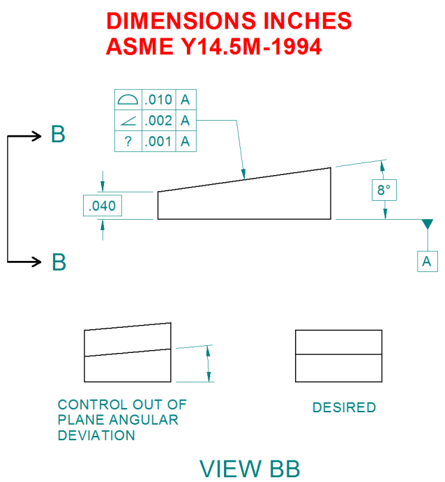
OUT-OF-PLANE-ANGLE-CONTROL_help0j.png


Trying to control the top angled surface, control of angle is more important than overall location.

Specifically looking to add control on the 'out of plane' angle. Something like any 'line element' in that orientation should be parallel to datum A within .001.

Seems profile of a line could do this, but how to express it. Does putting it in the existing FCF work or seems that may be confusing.

Thoughts?

Thanks.

Posting guidelines faq731-376 (probably not aimed specifically at you)
What is Engineering anyway: faq1088-1484
 
Replies continue below

Recommended for you

Simply apply parallelism callout to A with additional note EACH ELEMENT below. Similar to fig. 6-16 from '94 standard. You may also want to add secondary datum reference to that callout in order to unambiguously define direction of these linear elements.
 
Doh - thankyou pmarc.

I had the standard open at the page before!

Posting guidelines faq731-376 (probably not aimed specifically at you)
What is Engineering anyway: faq1088-1484
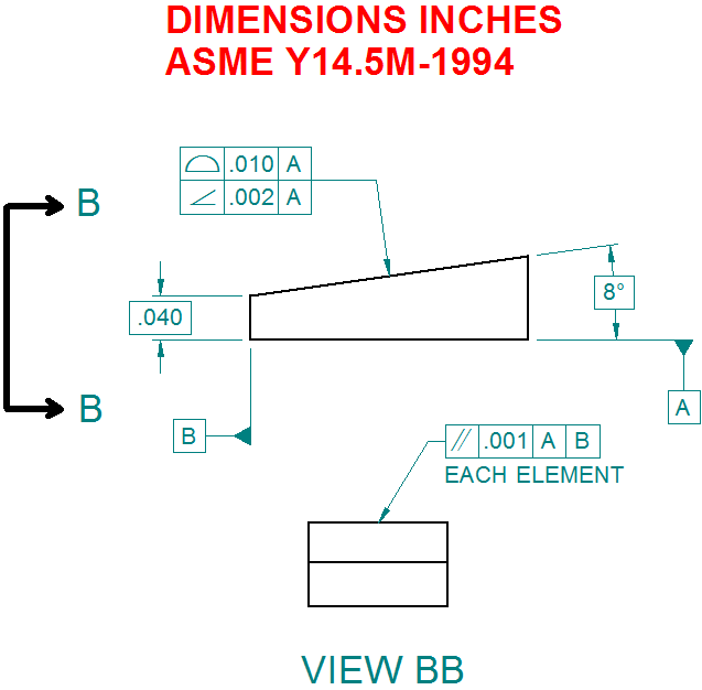
 
Interesting case! I'm wondering if datum B should be on one of the side face instead. This way, for each section, the tolerance zone will be parallel to datum A and then datum B will define unambiguously the orientation. Am I thinking this right?

Your file's link is:
2JL
Ps how do you add you pict directly inside the post?
 
2JL,

Your proposed datum B is not parallel to the line elements I'm trying to control so no, it's not correct.

download.aspx


You could potentially add a second line to the FCF with perpendicularity to your proposed datum B if that better reflects part function but in my case it doesn't.

There are 2 image related buttons on the ribbon bar at the top of where you type to post, one is to insert an image from somewhere online, the other is to upload an image and then insert it. You can also code it using TGML.

Posting guidelines faq731-376 (probably not aimed specifically at you)
What is Engineering anyway: faq1088-1484
 
OOPS! Somehow I was thinking about angularity instead of parallelism! Sorry about that!
 
I have never been confident that I understand the "each element" control, and paragraph 6.4.3 of the -2009 version is not terribly descriptive, in my opinion.

Could you explain the practical application of "each element" in that parallelism control? Does it apply to the edges of the face(s)? Does it apply to any linear measurement (parallel to the datums referenced) taken on that flat surface? Is it simply "best practice" as to how many 'lines' you inspect?

_________________________________________
NX8.0, Solidworks 2014, AutoCAD, Enovia V5
 
Functionally, I'm looking to minimize out of plane tilt per my sketch.

Figure 6-16 is pretty clear in the -1994 version with several lines of description below it, but the text of 6.5.5 is fairly brief.

As to how to inspect it - not my problem as I'm the designer not QA.;-)

Posting guidelines faq731-376 (probably not aimed specifically at you)
What is Engineering anyway: faq1088-1484
 
JNieman said:
I have never been confident that I understand the "each element" control

I am trying to see it as "Straightness with datum" (if you can think of Parallelism/Perpendicularity/Angularity as "Flatness with datum")

:)

"For every expert there is an equal and opposite expert"
Arthur C. Clarke Profiles of the future

 
Thanks.

I was just wondering if the angularity would be checked only at the verteces. This would allow for the middle of that face to sink (or dome upward) anywhere within the .010 profile tolerance zone. That would not be in line with your intent, I don't think. So I was thinking I may be confused on 'each element'... BUT I do believe your INTENT is quite clear - I think any "reasonable" person would see it and know "what to do".

_________________________________________
NX8.0, Solidworks 2014, AutoCAD, Enovia V5
 
KENAT,
Regarding your post from 15 Sep 15 22:29, yes, this is how it could be done, but...

2JL's idea to have one of side faces as datum feature B is not incorrect, even though datum B derived from that feature would not be nominally parallel, but perpendicular to the line elements. The role of a secondary datum feature reference in that kind of callouts is to constrain rotational degrees of freedom of the line elements.

There is no example in the '94 standard, but in the '09 version you may take a look at fig. 6-4 to see what I mean.
 
Status
Not open for further replies.

Part and Inventory Search

Sponsor