Eng-Tips is the largest engineering community on the Internet

Intelligent Work Forums for Engineering Professionals

Convergence problem / Discussion

Status
Not open for further replies.

cirokos

Civil/Environmental
Apr 11, 2022
63
0
0
GR
Hello everyone,

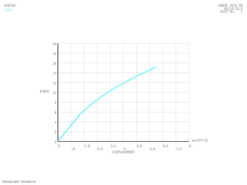
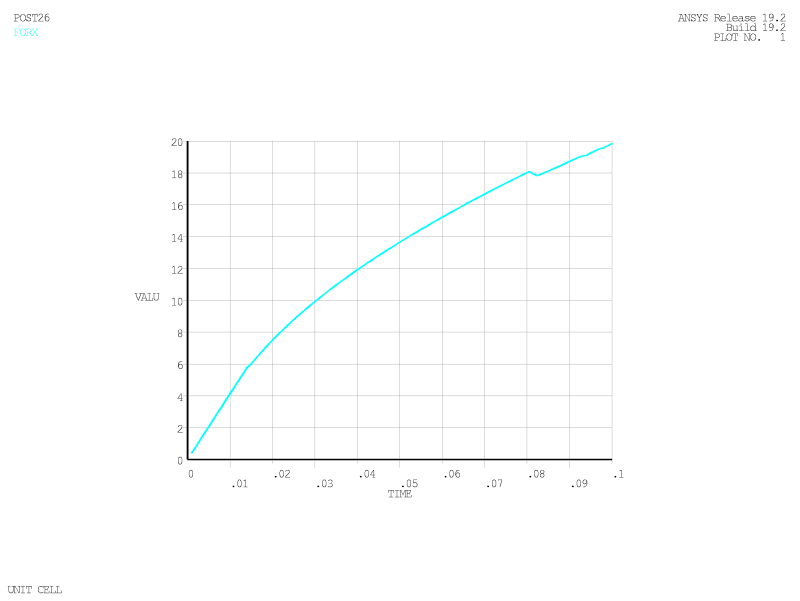
I am running a nonlinear analysis with displacement control. The analysis always stops at the same point producing the same graph of force displacement.
does this mean it reaches the limit of the structure?
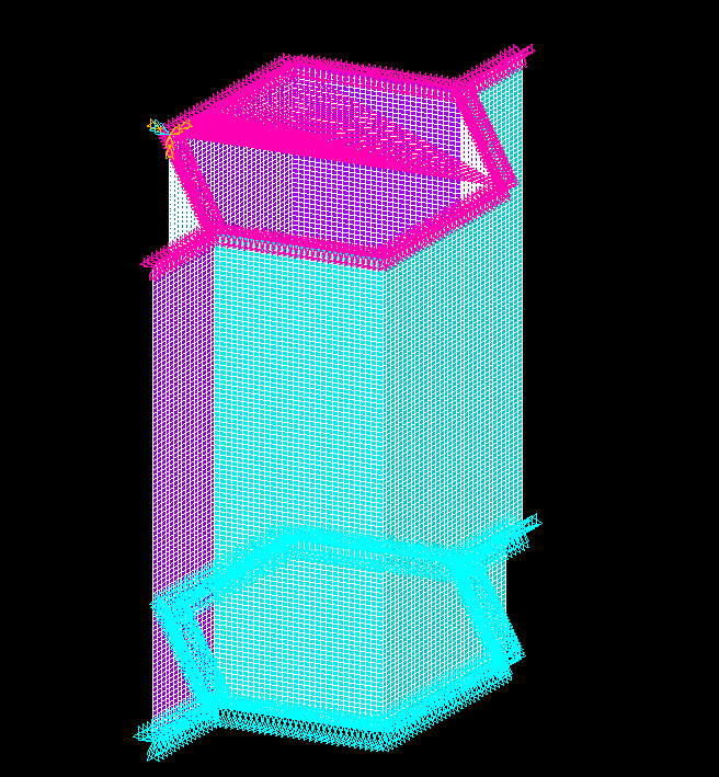
Material nonlinearities and large displacements are enabled
Displacement controlled loading
elements used shell181 ( Ansys Apdl software)

What approach should I follow to understand what's happening?
 
Replies continue below

Recommended for you

Can you say more about the analysis (geometry, mesh, material model, boundary conditions, loads, interactions and so on) ? Can you share the F-u plot ?

Perhaps it reaches buckling/collapse which cause problems for standard N-R solvers. Try with arc-length or dynamic solver.
 
So,
geometry: hexagonal cell dimensions angled walls 3mm horizontal also 3mm
mesh: shell181 with element size 0.1
material model: young modulus 70GPa v=0.33 Non linear properties: Bilinear isotropic hardening using von Mises or Hill plasticity with tangent modulus 0
boundary conditions: restricted at the bottom (UX,UY,UZ =0) top rigid region (cerig command)
load: displacement on a master node at the top

what interaction would you like to give?
These is the F-U plot ( If I increase the displ the solution stops at the same point )
HC_MODEL1000_lou3v8.png


I will try the arc-length method to see if the results are any different
Update: Tried arclen method but the solution keeps collapsing
 
please show a) picture of the model with loading and bc's, b) picture of the deformed geometry at max load.

have you run a linear buckling analysis?
 
This is the model with the BC and the loading (the purple,on top)
Screenshot_2022-11-04_225638_pxw9qr.png


Displacement at max load :
Screenshot_2022-11-04_232401_rkti0x.png


And von miss stress at max load :
Screenshot_2022-11-04_232505_sa7pdd.png


I haven't run a linear buckling to get meaning full results.
 
so the cell walls appear to be buckled, so no surprise that the loading has reached a maximum. getting the model to run under displacement loading to track the collapse may be difficult.
 
FEA way
You propose I run a linear buckling analysis and then update the geometry with a mode from the buckling one and see the changes?

SWComposites

It is a bit more challenging. I could change to force control
 
The standard way to find a collapse load is to run linear buckling analyses and add a scaled mode shape as an imperfection, as FEA way suggested.

If your solver type is Arc-length, it should be able to trace a collapse past the point of maximum load. Something seems fishy here. Are the elements locking-free (shear & membrane)? What is the geometric non-linearity: von Kárman (quadratic strains coupling membrane and bending modes, small displacements) or something else? Is the calculation performed with respect to current geometry (updated lagrangian) or initial geometry (total lagrangian)?
 
What do you mean by scaled mode shapes?

The model is with the initial geometry and elements are with bending and membrane
 
For anyone following this post.
I implemented the recommendations you proposed they worked. The structure seems to have gone further and this is the F v U curve. I don't know how to justify these results.

XXX006_kbc1nl.png


Thank you for the help you provided!
 
what do you mean by "justify"? the loading is compression, correct? have you compared the results to that published in the Hexcel core data sheet? (you will need to convert from total area stress in the datasheet to loading on your model section).

also, have you used 2x thickness for the a) the walls with free edges in your model, b) the walls parallel to those free edge walls? core is made with foil ribbons bonded together so those "nodes" are 2x foil thickness.
 
SWComposites

No, it's shear load. I haven't compared to data sheets. Will this give some sort of validation?

Also, haven't modeled the 2t thick of the walls.
 
congratulations on even asking the question "how do I validate the model ?" ... and not just believing your results.

Apologies, TLDR ... what are you modelling ? what material ?
it looks like a small hex cell, 1/8" each wall. With that dense mesh you're entering the "molecular" zone, and the FEA round off error is becoming significant.
this hex doesn't live on it's own ... is it a cell of a sandwich panel core ?

To properly validate your FEA you need some real result, the closer to your actual structure the better.

Ideally, you do a test of your structure, and see if the FEA predicts the (approximately) right strength and better if it predicts the right failure mode.
Alternatively, you can test some "representative" of your structure (like maybe a flat panel). Better if the FEA of the test specimen predicts the same failure mode as the real structure.

If this is the core of a panel, I believe you are "fooling" yourself. I believe there are many failure modes, and modes where the faces interact with the core, and so modeling the core in isolation is "pointless". But maybe I'm wrong ?

"Hoffen wir mal, dass alles gut geht !"
General Paulus, Nov 1942, outside Stalingrad after the launch of Operation Uranus.
 
By scaled modes shapes I mean mode shapes from buckling analysis (eigenvectors) assigned some physically realistic maximum amplitude, which in your case would be the expected size of physical imperfection. Procedures for this should be available in ANSYS.
 
Modeling the whole geometry could take to much computational time and effort. How can I determine the best dimension ( BC etc ) in order to have comparable results with the whole geometry?
I don't know if I am explaining this correctly
 
can you do buckling analysis with super elements ?

condense various pieces of your model to a small set of freedoms, which join together to make the whole.
writing it that way, I think I've answered my question ... no (or probably not)

but how much time is "too much" ? let it run over the weekend, if you must. I recently had a model of 1e6 elements, took a couple of hours ... was great ... started it, went off and did something else, came back and it was nicely cooked !

"Hoffen wir mal, dass alles gut geht !"
General Paulus, Nov 1942, outside Stalingrad after the launch of Operation Uranus.
 
I haven't really used super elements to model anything...
I am running all of the analysis with a laptop so it's a bit harsh on it.
1e6 element will take the whole weekend to finish even more!

I have done buckling analysis on the unit cell not the whole structure.

Also changing the KEYOPT8 from default to the one that Stores data for TOP, BOTTOM, and MID for all layers; applies to single- and multi-layer elements changed my results. Why is that?
 
Status
Not open for further replies.
Back
Top