Continue to Site

Eng-Tips is the largest engineering community on the Internet

Intelligent Work Forums for Engineering Professionals

  • Congratulations KootK on being selected by the Eng-Tips community for having the most helpful posts in the forums last week. Way to Go!

Converting ASD to simple Factor of Safety

Status
Not open for further replies.

mfritze

Mechanical
Aug 12, 2013
32
Hello,

I am a mech. engineer who often uses AISC design guides for designing frames and other steel structures. In our industry we are required by mil. spec to have a factor of safety of 5X to ultimate on the equipment we design/build. When using the ASD method what are your thoughts on coming up with ASD inputs corresponding to a simple FOS? For example, what I typically do is take Load*5/1.67 as my input. As I understand this would account for the 5X factor of safety with an omega=1.67.

Thanks
 
Replies continue below

Recommended for you

Omega varies depending on the limit state, right? Make sure you don't multiple that ratio to the frame loads, rather only when comparing capacity and demand.

The real question is if using that ratio reasonably approximates the goal of providing the same probability of failure per the Mil spec. I am not familiar with the Mil spec, but I suspect your method is reasonable in most cases.

One in the hand is worth two in the bush.
 
I am not familiar with AISC codes, or N America standard practice, but as far as I am concerned an ultimate FoS of 5 means that the structure should not fail when subject to the specified load x 5.

The only way to check that is to calculate the failure load.

Doug Jenkins
Interactive Design Services
 
All AISC design provisions start by calculating the nominal capacity, i.e., a capacity without any safety factor. The design spec is equally valid for ASD and LRFD type analysis. Both start from the nominal capacity, then adjust by either safety factor (ASD) or resistance factor (LRFD). Simply calculate the nominal capacity then divide by your Mil Spec factor of safety of 5.0 to get an allowable capacity at working strength loads.
 
ASME BTH is a design guide for below-the-hook lifting assemblies. While it might not be applicable to your work, it might be of interest to look through. It is based on AISC design, but has the factor safety/ design factor broken out.
 
Whenever possible we try to work these safety factors into the allowable side and even then it is complicated because many of the equations use Fy and the ratio between Fy and Fu is not constant.
For A36 steel and using Fu = 58 ksi then 58/5 = 11.6 ksi and 5/1.67 = 2.99 or 3 and 36/3 = 12 ksi 5:1 on ultimate = 3:1 on yield. Note the reciprocal of 1.67 is the 0.6 in Fb = .6 Fy.
For A992 steel or other Gr. 50 material where Fu = 65 then 65/5 = 13 ksi and 50/3.85 = 13 ksi. 5:1 on ultimate = 3.85:1 on yield.
Attached is a chart showing AISI (cold formed steel) safety factors. I have not seen a similar chart for AISC or ever tried to derive one.

is a link to a pdf article that has tables showing Fy and Fu for different grades of steel and fasteners.
 
I often have to show FOS when working on machines. I just take the extra step of calculating yield/stress or tensile/stress and show the FOS. I've found manipulating the loads provides for confusing reviewers and adding unnecessary explanation and introduced doubt. The few minutes it takes to hand calc the FOS is worth it in my opinion.
 
steele - you are definitely echoing what I was mentioning.

One in the hand is worth two in the bush.
 
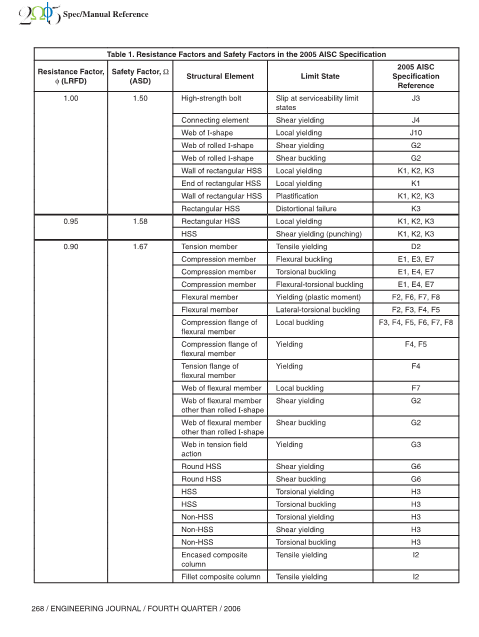
AISC's Engineering Journal article from 2006, Q4 entitled "Technical Note: Determination of Allowable Strength Design Safety Factors in the 2005 AISC Specification" Link lists safety factors and resistance factors based upon element type and limit state.

Part copy:

Capture_uasbr4.png
 
Status
Not open for further replies.

Part and Inventory Search

Sponsor