Continue to Site

Eng-Tips is the largest engineering community on the Internet

Intelligent Work Forums for Engineering Professionals

  • Congratulations pierreick on being selected by the Eng-Tips community for having the most helpful posts in the forums last week. Way to Go!

Converting spline coupling into standard flange coupling 1

Status
Not open for further replies.

edison123

Electrical
Oct 23, 2002
4,490
If I am in wrong forum, please guide me to the right one. Thanks.

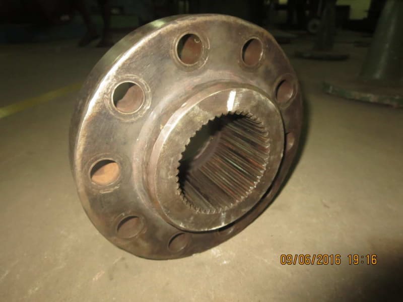
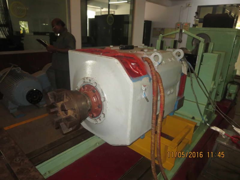
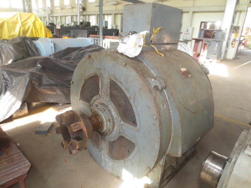
We have received a GE 1000 HP, 1200 RPM DC motor with spline coupling area on the shaft as below. The driven equipment is a 1000 KVA AC alternator.

Img-2_tvtsxz.jpg


Img-6_lgc5mx.jpg


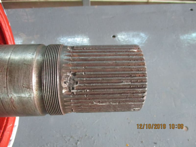
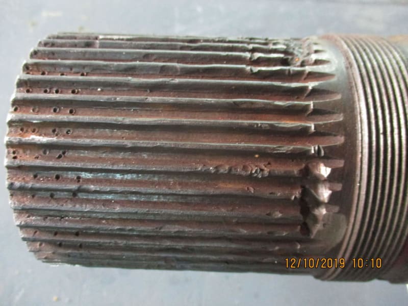
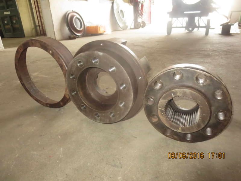
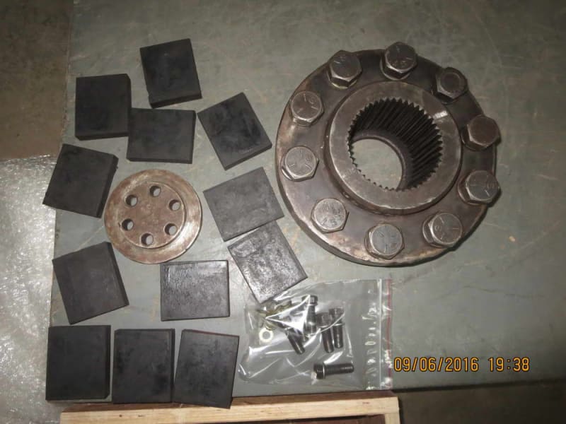
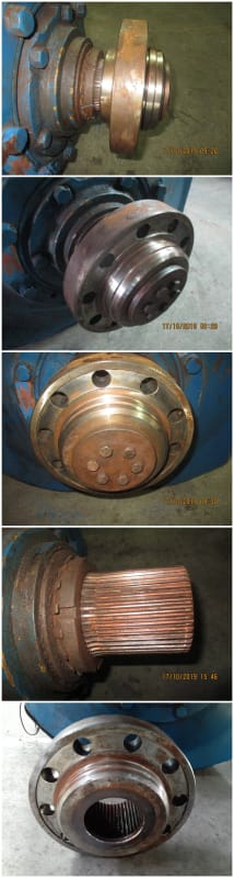
As you can see, there are plenty of damages/misaligned grooves in the spline area of the shaft.

I am not sure how good is the contact area of the shaft with the spline coupling with so much damages.

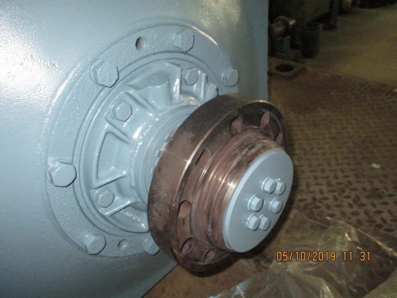
I plan to replace this splined shaft with a new shaft having a standard keyed flange coupling like this.

x_nycpih.jpg


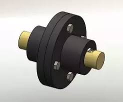
Do you mech gurus see any issue with such a plan?

Muthu
 
Replies continue below

Recommended for you

Much more information is needed.
Pictures or drawings showing the general arrangement for a start.

For instance:
- If both machines have their own thrust bearings The splined coupling //may//have been chosen to provide mandatory axial compliance when thermal expansion occurs.

- Perhaps the splined coupling was chosen to make installation/assembly of the two machines possible.

- On industrial splined couplings the splines are often "crowned" and the power transfer planes are separated to provide tolerance for shaft-to-shaft misalignment.

What does the thread on the shaft do?
 
Thanks Tmoose.

Both machines have their own cylindrical roller bearings (thermal axial expansions take place in these roller bearings of each machine) and ball bearings, which take care of the thrust load, of which there is not much since it is just a MG set.

Both machines have their own couplings, spline coupling on the motor and cylindrical bore flange coupling on the generator. Both couplings are heat fitted at around 120 deg C.

The thread is for the ball bearing lock-nut.

Muthu
 
If this were my project, I would investigate whether I could implement a shrink disc connection - a lot more information would be needed to make that determination.
 
Please provide a picture and engineering cross section of the OEM coupling assembly.
I am thinking that the connection between the OEM splined hubs on the motor and alternator VERY likely consisted of rubber plugs or something with significant radial, axial and bending compliance.

The hard bolted flange coupling in the image you posted would have none of those.
Coupled machines NEED compliance between their shafts to prevent cage match death battles between the .001" differing demands of the two shafts.

As for the coupling hub>shaft interface, the spline should have worked just fine IF it was clamped hard axially against a shoulder, etc by the 6 bolted keeper plate.
The shot of the back (?) side of the lone splined hub shows no contact with a shaft shoulder etc.

If on the other hand the keeper plate butted against the shaft end, the splined hub was free to constantly wiggle and shift and the micromotions would fret and eat clearance into the splined interface 100% of the time in operation.
 
Thanks, Tmoose. I got more info now.

You are right about rubber plugs, both the motor and the alternator have bolted on lovejoy coupling units with rubber pads.

Motor coupling parts including the bolted on lovejoy unit

MCP_gvifam.jpg


Motor coupling with bolted lovejoy unit and the lovejoy rubber pads

mcp1_xpb4qw.jpg


Motor fitted with the coupling

MC_nqmekz.jpg


Generator with its own lovejoy coupling unit

Gen_fxmgpc.jpg


What if I reuse the bolted lovejoy unit of the motor with a cylindrical bore flange coupling so that the original compliance is met with?

Tomorrow, I am getting another motor with the spline coupling fitted on customer's site. I will post its on arrival picture.

Thanks once again for your tips and advice. Much appreciated.


Muthu
 
The photos of the spline coupling of the motor we received today.

Z_wens1v.jpg


After removing the front face lock plate, the whole coupling slid off the shaft by hand. At least the spline areas appear to be damage free both on the shaft and the coupling bore.

Muthu
 
Status
Not open for further replies.

Part and Inventory Search

Sponsor