Continue to Site

Eng-Tips is the largest engineering community on the Internet

Intelligent Work Forums for Engineering Professionals

  • Congratulations KootK on being selected by the Eng-Tips community for having the most helpful posts in the forums last week. Way to Go!

Conveyor Gallery Bridge Structural design 1

Status
Not open for further replies.

StrP88

Civil/Environmental
Feb 4, 2016
189
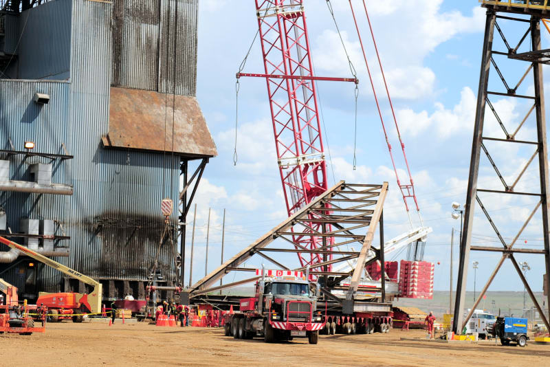
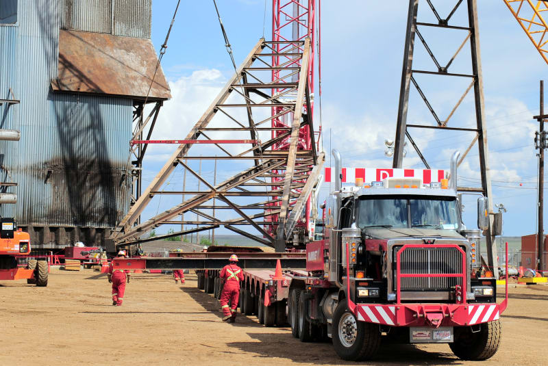
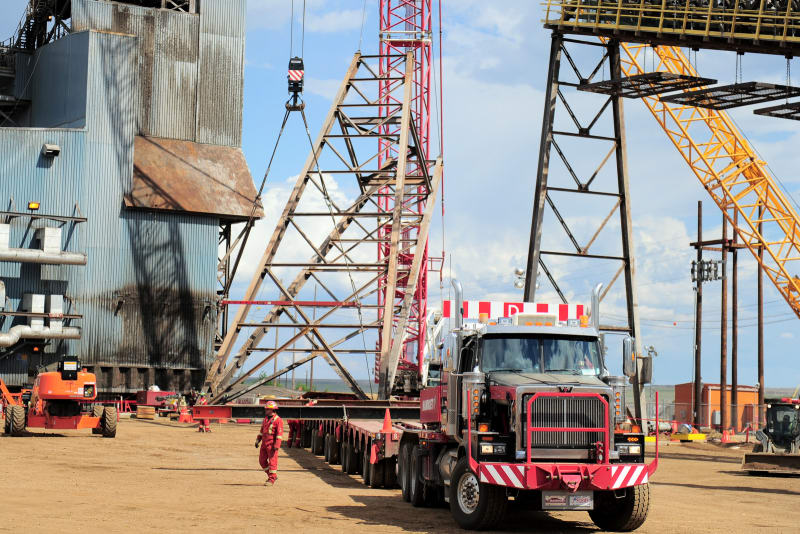
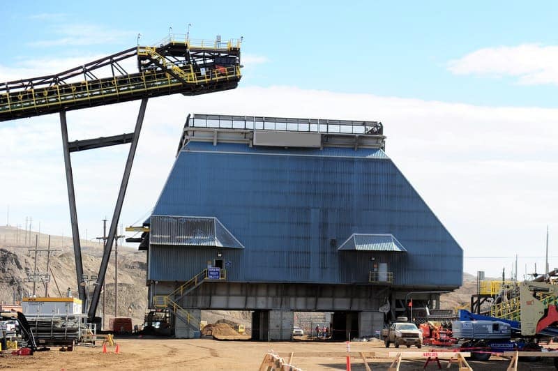
I am looking for a source that kind of explain structural design of conveyor truss and trestles.
Also kind of struggling understanding the supports of conveyor on top of trestles? Whats a fixed support will look like and what a roller will look like on top of trestle?

How are these trusses just individual segments that will install individually on top of trestle? Do they connect them? Do we design the truss continuous over trestle?

What type of support do we use at each end of whole thing? Do we use the pinned on the very top? or on their bottom?

Any book points these things out? Most books I seen are about belt and mechanical side of conveyor rather that supporting structure?

Any article, book, power points, training? I appreciate your help

 
Replies continue below

Recommended for you

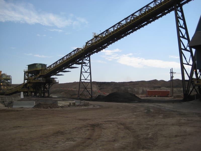
I don't have any book references, but I was involved in the design of a conveyor system at a nickel processing plant about 10 years ago:-

We had trestles with pinned connections to simply supported trusses (trusses from both directions supported on a common fin plate with a pin). Base of the trestles was nominally pinned so that it could lean over with any thermal expansion. At some locations we had slotted holes with the pins to take up the thermal expansion lengthways and isolate certain structures from taking any loads from seismic parallel to the trusses. Trestles took the lateral load perpendicular to the truss with a common pad foundation with two pedesdals for the trestle legs. In-plane with the truss any lateral loads were taken by the connection back to the ground at end of the conveyor or to the structure which the conveyor was connected at the higher end (typically an open framed tower or another building structure.

We had the pins at the underside of the truss. Conveyor belt simply ran between the two truss ends with rollers close to the ends of each truss.

Very high 4.5kPa wind loads from memory as subject to cyclones. We didn't have any continuous trusses over trestles, I think that just creates problems if trestles go in too high/low with alignment/tolerances and assumptions on loading to each support. We also had to fit it all into containers and ship it so tried to avoid costly splices.

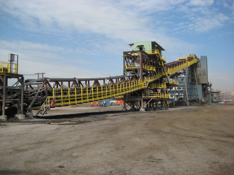
general truss arrangement we had, you can see the pinned connection at the ends
DSC00026_ldssts.jpg


Very small trestle to give you an idea of the arrangement we had (this was reusing some existing foundations from one of the many conveyors being replaced.
DSC00006_wgublp.jpg
 
Agent666 (Structural),
Thank you so much for taking time to respond and include photos. I greatly appreciate it.
Since you had experience in design of conveyor support structures, I will extend more questions

1- Do we design conveyors in a way/lengths that simply supported spans between the trestles and each end? Dont we design them continuous over the trestle?
2- What is the practical gap or distance for thermal expansion between the two trusses?
3-Would we locate thermal expansions on top of the trestle or it can be located at location between the two adjacent trestles?
4- Is there enough room on the top beam of the trestle so the two trusses's ends can be sit on that beam? Shall that beam have a wide flange to be able to accommodate two trusses on?
5- The trestle frame, do they typical design it as a moment frame or it is pinned frame (meaning all struts are pinned to trestle legs)?

Sorry to bombarding you with all these questions. I appreciate if you can help me answering these questions

Thank you so much
 
You should be getting a lot of this from the conveyor manufacturer (i.e. where they expect a "pinned", "roller" or "fixed" support). As far as the thermal growth thing goes.....that's another question for them. (I.e. have they considered it? Do they need a slide support?)

And yet another question for them is the unbalanced force from the conveyor. (A lot of times they've left figuring that to me.)

In my experience, for a lot of light conveyors, I've used hanger supports for a lot of it. (Sometimes hangers that go up to roof trusses.) But eventually you will need to pay the piper and have a more substantial support somewhere.
 
WARose (Structural)
Thank you for your comment. The manufacturer is out of business and no drawings are available. It is all on me to decipher.

That's why I am trying to learn it. May I ask the slide support you refereed is the roller or is different animal?

Without drawings how to figure out the Thermal expansion joint on the structure and how by the look of the support I determine if it is pinned, roller, slide, fixed in conveyor trusses?

Thank you for helping me out understanding it
Respectfully
 
StrP88:
It is crazy as hell that a company will spend hundreds of thousands or millions of dollars for some equipment or a building and not bother the save the paper work on the purchase and a set of plans and specs., maintenance manuals, etc. Then, you are supposed to be a magician and figure out how it all goes together, and since you are an engineer, you shouldn’t need any experience with the structural systems either, just snap you fingers. Can you look at similar equip., maybe by the same manuf’er., on this job site; what about that manuf’er’s. equip. at other local facilities? What about materials handling associations, or conveyor manuf’ers. associations and their stds. and std. details? Would some other local builder help you out, maybe one who took over part of that earlier business, knowing that they will be at the front of the line for future maintenance business, etc. Many of the people here on E-Tips are really smart and helpful, but they aren’t right there to see the details and the fit-up, etc. And, use the phone, not email. You want a knowledgeable member of the engineering dept., not the phone switchboard here they throw out an answer so you go away.
 
If you don't have any drawings on this thing.....sounds like a lot of field work (pulling tape) followed by some analysis. How to support it will (ultimately) be based on that. But you should be able to tell a lot from support details. (I.e. a 4 bolt (post) base will be modeled as a "fixed" base and so on.)

Hopefully a mechanical engineer is involved in this so he might be able to assist to a certain degree.
 
Not sure of the material your conveyor will carry, but in mining and materials handling, most conveyor trusses are simple span. And probably the most common truss supports are two legged "trestles", often using circular hollow sections. While these usually have 4 anchor bolts, they are assumed as pinned base, with the longitudinal forces taken by bracing or anchorage at discrete points. The trestles without bracing are allowed to tilt parallel to the conveyor. Slide connections can be used at a braced trestle if required for temperature.
 
1- Do we design conveyors in a way/lengths that simply supported spans between the trestles and each end? Dont we design them continuous over the trestle?
Most conveyors are designed as simply supported spans. As noted earlier if you have continuous spans you can (and probably will) have issues with dealing with the vertical tolerance of the supports and supporting the truss at the supports. For example say you have one end supported on a beam that deflects 20mm, and the central & other end support on a trestle. This just wouldn't be compatible.

2- What is the practical gap or distance for thermal expansion between the two trusses?
You need to work this out based on expected temperature difference and the coefficient of thermal expansion.

3-Would we locate thermal expansions on top of the trestle or it can be located at location between the two adjacent trestles?
We just accommodated it at the pin support with a slotted hole, alternatively you could cantilever the truss over a trestle and not have it connected to the adjacent structure (belt continues) to create a physical break.

4- Is there enough room on the top beam of the trestle so the two trusses's ends can be sit on that beam? Shall that beam have a wide flange to be able to accommodate two trusses on?
Again up to you, you can always make the location of the support wider locally. But yes two trusses are typically supported from the one trestle rather than providing two trestles. [Edit, refer to my second photo for example]

5- The trestle frame, do they typical design it as a moment frame or it is pinned frame (meaning all struts are pinned to trestle legs)?]
Depends on the type of construction, model and design it based on the details you plan on providing. I believe you should always model them fixed and pinned just to justify that taking them as being pinned isn't missing out on any significant moments that might develop for example. Typically trestles are braced to limit horizontal deflections, but sometimes you cannot avoid vierendeel truss arrangements (for example conveyors stacked on top of one another with openings in the trestle for the lower conveyor truss.


The answer to your questions very much depends on your constraints and arrangement.
 
Dik said:
Didn't have a book, but, this is what I ended up with.

Your truss vertical brace is not optimized. You should re-arrange the vertical brace so that they are only tension brace and it will end up with small member size and saving steel.

AISC Steel Connection Design Software
 
amec2004 (Aeronautics)
So could you please if you can show me in conveyor industry what a pin/hinge looks like on top of the bent and what a roller/ rocker looks like on top of bents and is slide support same as a roller?

Why the make the legs of the bents slopes rather that complete vertical?
So I noticed above most of bents under the two trussed end their is one support so then how could each truss be simply support on bent? I thought if they are simply support I have to see two separate supports on top of each bent at each side of trusses, however I see only one !!!

Any pics or sketch can help

I appreciate for helping me understand this industry

Thank you
 
StrP88 said:
what a pin/hinge looks like on top of the bent

Truss Pin/Hinge Support at top of bent

Truss-Support-at-Bent_qew86c.jpg


StrP88 said:
roller/ rocker looks like on top of bents and is slide support same as a roller

We don't do roller support. What we did is the cantilever at the last bent and allow it to expand.

Last bent to be cantilever and allow it to expand freely

04-Last-Bent-As-Cantilever_ichfmt.jpg


StrP88 said:
how could each truss be simply support on bent?

We normally design the bent as panel, not tower, and all longitudinal force go to drive station or last bent touching the ground.

We normally design the bent as panel

01-Bent-As-Panel_hqo5zr.jpg


All the longitudinal force goes to drive station or last bent

02-Bent-Tie-To-Drive-Station_onerl6.jpg


If you want mid bent take the longitudinal force, design it as tower and here is how to achieve truss/bent as pin

03-Bent-As-Tower-For-Pin_codmag.jpg


Best tool to design steel connection as per AISC code AISC Steel Connection Design and Steel Connection Design Examples


AISC Steel Connection Design Software
 
amec2004 (Aeronautics: Thank you very much for great information. And my apology for bugging and questioning.
When you said, "We normally design the bent as panel, not tower, and all longitudinal force go to drive station or last bent touching the ground."
Do you mean the bents are not stable by themselves in the conveyor length direction and they gain their stability in that direction from bridge trusses?

So if a bent loses the trusses on top it, it can fall down since nothing is holding it up?

Is there any text book or handbook, article going over these subjects?
I am desperately looking for a sample calculation for educational purposes only. Can you help me out?

Very much appreciated.
 
StrP88 said:
Do you mean the bents are not stable by themselves in the conveyor length direction and they gain their stability in that direction from bridge trusses?

Bents are not stable in longitudinal direction if they lose linking trusses, but what I am talking is not about this topic. What I am talking about is the "Lateral Resistance System" when you design a structure, in another word you have to think about how the lateral loads, wind, seismic, belt tension etc, are transmitted to the foundation in an economical way. You design the bents as tower will cause more steel and piling in a 3D tower base, you design the bents as panel and let the drive station take the longitudinal load will be more economical.


StrP88 said:
So if a bent loses the trusses on top it, it can fall down since nothing is holding it up?

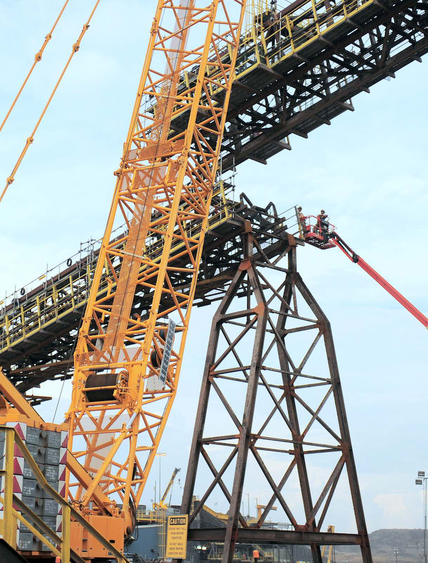
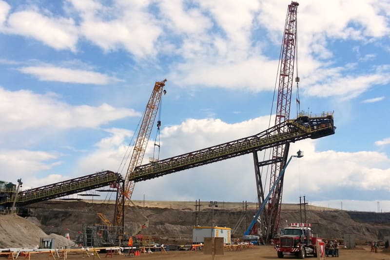
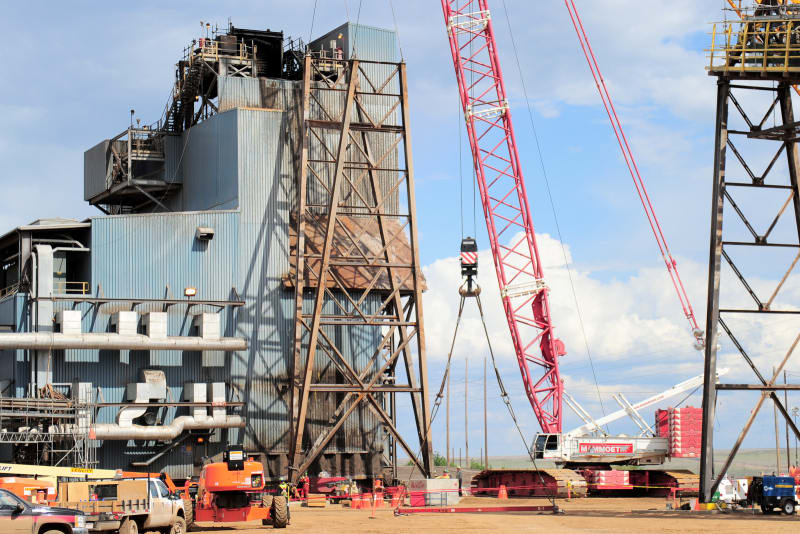
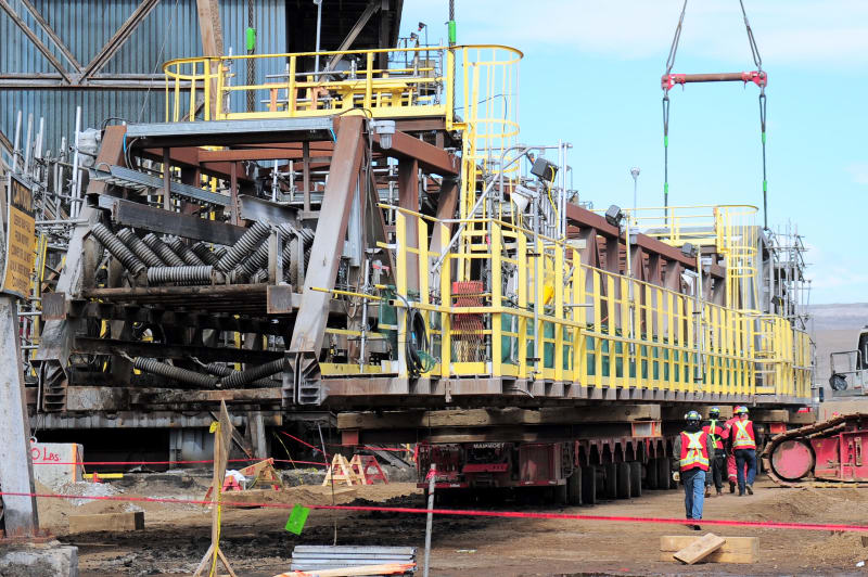
If you design it as panel, yes it will not self-stand in longitudinal direction, you see the photos below

Truss been taken out

20130516_145742_z83pjb.jpg


The panel fall off

AKG_8870_zkuygc.jpg


AKG_8881_evggu0.jpg


AKG_8884_vgz4gg.jpg


Can this bent stay without truss ?

AKG_6520_ilcumx2_ic1wrl.jpg


AKG_8895_eaqqgn.jpg


That's truss been taken down

AKG_8312_upe260.jpg


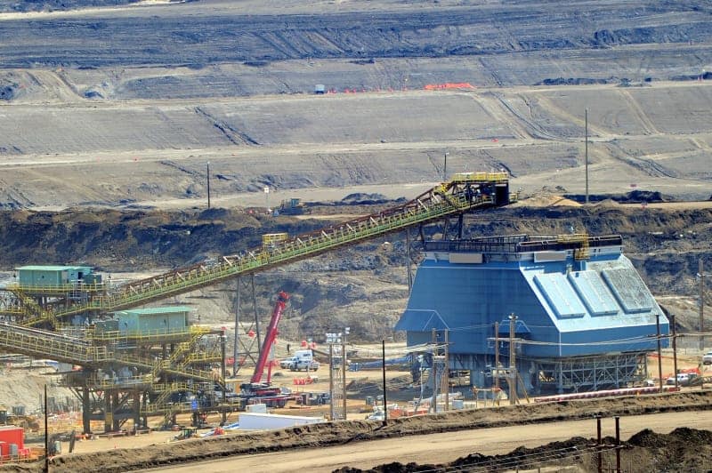
That's overall bird view

AKG_7200_exzp48.jpg


That's overall bird view

AKG_7186_ztipyv2_pop0mf.jpg


Best tool to design steel connection as per AISC steel code AISC Steel Connection Design and Steel Connection Design Examples


AISC Steel Connection Design Software
 
amec2004 (Aeronautics)
Thank you so very much for generously sharing your knowledge and the photos.
As I love this specialty and learn you are excellent at it. Couple more questions - may be dumb questions

May I ask if you know the reason that why the bents get narrower at top. What's the benefit of doing it? Rather having the legs perfectly vertical.

Does'nt it making the legs sloped add to complication at base plates?

Another question are the bents at the base pin connection in the conveyor direction and fixed based/support at the direction perpendicular to the conveyor?

Also do you typically sit the bents on a pile foundation?

Thank you so much for your kind share of knowledge
 
StrP88 said:
why the bents get narrower at top. What's the benefit of doing it? Rather having the legs perfectly vertical.

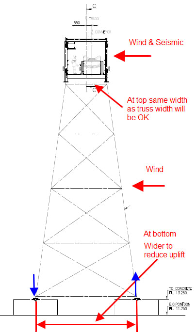
The bent get wider when going down because we need larger lever arm to reduce uplift due to over turn moment. See sketch below

01-Bent_cc8h9s.jpg


StrP88 said:
Does'nt it making the legs sloped add to complication at base plates

Not at all and provide what is needed to save the steel cost, see those tapper section frame in steel building?

StrP88 said:
Another question are the bents at the base pin connection in the conveyor direction and fixed based/support at the direction perpendicular to the conveyor?

All pin in both directions. At the direction perpendicular to the conveyor, once braced to the base plate, there will be no moment even you design as it as moment connection.

Remember !!! same in steel connection where a joint has brace-beam-column conencted, that joint beam-column part will have zero moment even you design it as moment connection.
if a moment frame works together with braced frames, that moment frame base will have zero base shear and all base shear go to braced frame base.

Rule of thumb, strong/tough/ siff guy get all the force !

StrP88 said:
do you typically sit the bents on a pile foundation

Case by case, I had a project in the Canadian North territories where there are all permafrost soil and only one month window for construction. In this case piling or cast-in-situ concrete is impossible.
Only practical foundation is precast footing, but it will be tricky when the huge uplift come in and the footing will slide when there is zero compression.


Best tool to design steel connection as per AISC steel code AISC Steel Connection Design and Steel Connection Design Examples


AISC Steel Connection Design Software
 
Just to clarify, when you use the term "gallery", do you mean a box truss that surrounds the typical conveyor frame and allows it to span a further distance that the conveyor frame itself?

 
Status
Not open for further replies.

Part and Inventory Search

Sponsor