Continue to Site

Eng-Tips is the largest engineering community on the Internet

Intelligent Work Forums for Engineering Professionals

  • Congratulations waross on being selected by the Eng-Tips community for having the most helpful posts in the forums last week. Way to Go!

Cooling loop valve 2

Status
Not open for further replies.

itsmoked

Electrical
Feb 18, 2005
19,114
I have a cooling system as seen below that runs water/ethylene glycol mix to cool 13 zones via solenoids.

The pump charges a manifold that the zones draw from. Since temp controllers run the valves none can be open or most of them can be open. All of them are never open though perhaps half could be at once.

I want to spec a valve to bypass when needed to try and keep the supply pressure constant thru the loops while also avoiding dead-heading the pump. I have no idea what the correct term for this particular valve would be or where I should look for one. Given the details I've provided can I get some direction on what and where I should get one, preferably at the usual suspects.
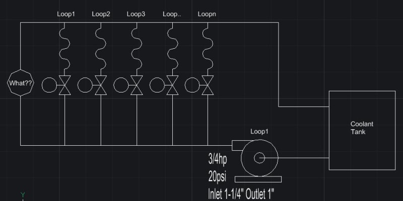
Hotloop_qjor4i.jpg


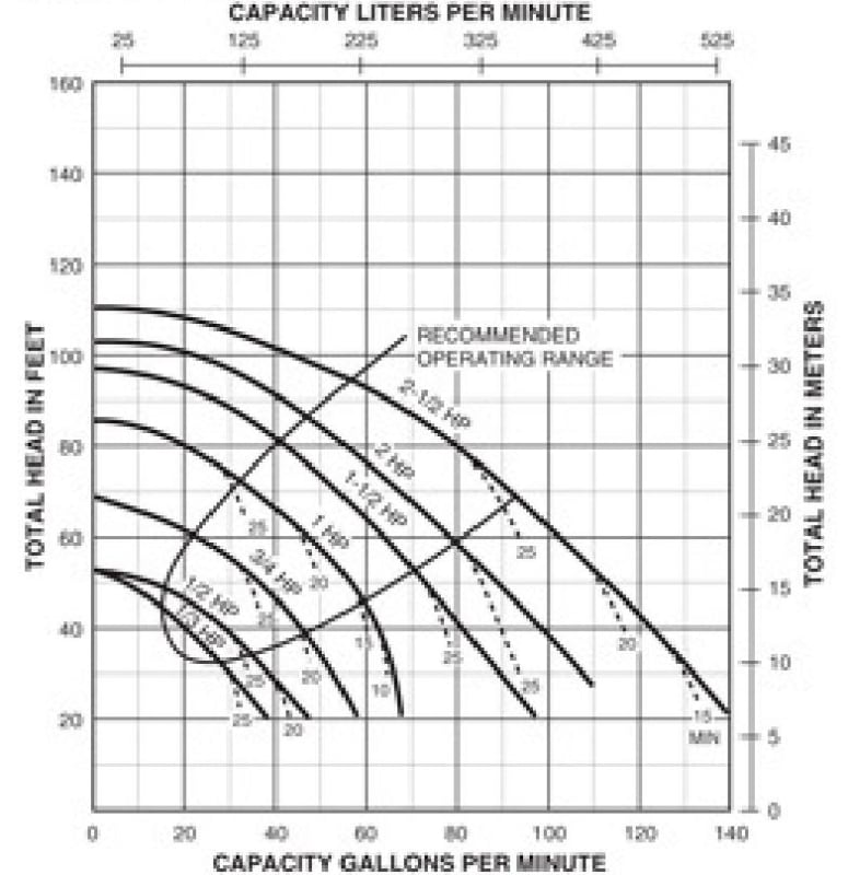
Hotloop_Pump_Curve_lkxsh1.jpg


Keith Cress
kcress -
 
Replies continue below

Recommended for you

I'm sure the other guys will suggest something better, but you can maybe just employ a simple auto-operated pressure control valve with its pressure control on the intake.

Spirax, Emerson, Masoneilan and all the other control valve suppliers will probably have something that can work in this scenario.

Daniel
Rio de Janeiro - Brazil
 
If one valve open is sufficient to meet your minimum flow requirements I suggest you stop the pump when there are no valves open. The pump will tolerate deadhead operation and your system has some thermal mass so you may be able to utilize these to factors to prevent short cycling of the pump. If you can keep it under 1 start per 10 minutes you're golden.

A pressure regulating valve that uses proportional control will not be ideal, it may chatter under certain conditions. A PID controlled valve would be preferred here.
 
Keith, just to add to my previous post, *I* usually prefer a control valve controlled through a control loop with a PIT, but that obviously require more instrumentation which I don't know if it is really necessary to your system.

I'd set up the pressure on the header to be whichever the pressure needed to not go below the minimum stable flow on the pump considering the entire range of suction pressures expected

Daniel
Rio de Janeiro - Brazil
 
Cla-Val is a very well known brand for self-contained hydraulic actuated water valves and have such for backpressure control. I have used them mostly in such service.

 
Normally I don't like running min flow valves like this on pressure control, but your rather small pumps have a quite drastic curve so in this case all you need is a back pressure valve set at as high a pressure as you can figure the pump is good for. Personally I would be looking at 30% of rated flow, so probably a bit higher than the operating range shown there, but also at least 10% below the dead head pressure.

There are many self contained / pilot operated valves, but Cla valve are a good one.

The other option is a fixed orifice sized for maybe 10-15% of flow with max differential pressure at close to dead head pressure, but then it operates all the time and you need to include this in the rated flow.

Very cheap and simple but has downsides.

but if you rarely operate all items open, how are you setting the duty point / flow for your system?

Remember - More details = better answers
Also: If you get a response it's polite to respond to it.
 
Tug; There can be extended periods of no valves open such as during daily startup when none of the zones are within 175F of their setpoints. After that all the zones tend to rattle on and off at least once a minute.

I was hoping to have a relatively constant pressure so the PIDs running the cooling have a steady zone pressure to work with, otherwise the PID comes up with 3 seconds for an output when if the pressure is low should've been maybe 7 seconds. Or, vice versa either of which screws up control.

danschwind; Thanks for the names but that has proven fairly useless. Their websites are bloated un useful crap and leave me expecting to find a valve after hours and hours only to find they cost $3k and have a month lead time.

I'm just looking for something I can get a McMaster-Carr or Grainger or Ebay or ? not a week of phone-tag with moneysentatives.

Isn't there some kind of pressure control valve with a plumbed outlet that I can route back to the tank? Set it for 18psi and call it a day?

Currently there is just a bypass valve they "leave open some". What a waste!

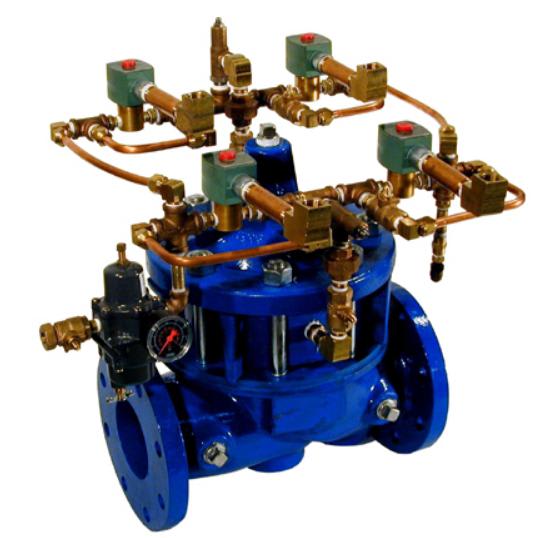
Snickster; I'm just seeing valves that are larger than the pump, flange mounted electronic controlled ones at Cla-Val.


Keith Cress
kcress -
 
Hi Little;

Can you cobble up a Cla part number in the area I'm working because I see only things like:

CLA_valve_ef4x0f.jpg


As for duty point or flow there is nothing but a manual bypass valve as mentioned, that's why I'm trying come up with something that can add a trace of control to this thing.


Keith Cress
kcress -
 
Or install an orifice if that's good enough. Can't get simpler or easier than that.

Calculate for say 15% of duty flow and leave the valve there in case you need all the pump power sometimes.

but make the orifice out of something strong and check it regularly as the erosion can be quite high. It really is a restriction orifice you want rather than a simple plate.

At this sort of power, the waste is not big.

Or just install a globe or needle valve and then adjust it to whatever flow you want and then add a cable tie to it so people don't fiddle with it.

Your posts are fluctuating between a full electronic PID loop with actuated valve to something you can get on ebay??

Remember - More details = better answers
Also: If you get a response it's polite to respond to it.
 
Standard approach is to install a min flow bypass that operates on flow control (for pumps running on fixed speed). FCV take off should be the first tee off the supply header, not the last. FIC closes the min flow control valve when total flow exceeds pump min flow. Some people prefer to size the control valve for close to max flow and operate on dPIC, so that dP at each loop control valve remains constant even while other consumers may swing up or down. I prefer the max flow - dPIC setup - it is more stable.
 
Itsmoked, if you want to maintain a constant pressure to simplify your PID control there are a few things that will assist in that goal.

Use a pump with a flat pump curve. Pressure will vary less with changes in flow.

Use a relatively large accumulator, one that can supply the flow demand of a circuit for at least a minute.

Use a VFD that sets pump speed based on the number of valves open. Run in open loop every time a valve opens and use PID to trim the output immediately after for constant pressure.

Combine all 3 for a most stable system.
 
Let's all get a bit real here.

This is a 550W / 3/4hp pump at 20 psi and a max flow of 50gpm.

You could probably just get a spring relief valve and set it at 60ft head.... then just adjust it a bit to get it to work as you want.

He just wants something cheap and easy.

Remember - More details = better answers
Also: If you get a response it's polite to respond to it.
 
There is one of those on my water heater.

Einstein gave the same test to students every year. When asked why he would do something like that, "Because the answers had changed."
 
Easy; Put a check valve after pump (probably go for a low pressure drop flap valve or equivalent.) Install a pressure switch at 15psi~ after check valve. When a cooling valve opens the pressure switch will kick on the pump. When all the valves close it will shut the pump off. Disadvantage is you'll lose thermal mass of the material in the coolant loop as it isn't circulating. This won't matter if you're trying to cool to ambient but if you're trying to cool to sub-ambient and it doesn't cycle repeatedly then there will be performance delays as coolant material cools. Make sure to 'tune' the pressure switch so it's not opening and closing rapidly when only one tank is open.

Medium easy; At the last (furthest) process make a 'short' between the supply & return side. Make this short out of 1/2" pipe so the pump can run constantly but if any of the valves open the bulk flow will be the process loop. This is effectively the orfice conversation above but just made from easy pipe. This will only work if pressure drop across the loops is relatively low. The method could be tuned a bit with a valve.

Hardest; medium except make the short out of full size and tie a NO valve on the short that is commanded in series with all your other valves. When one of the valves opens the NO valve controlling the short will close. When the valves are closed the coolant tank stays cool and pump can run at full flow. Difficulty in this can vary pending site configurations, the annoyance is running wires from pump controller to farthest connection. The gain here is full flow through processes without needing to worry about the losses through the short.

Better medium/hardest; medium/hardest + temp controller in the coolant tank to shut off the pump when the coolant tank is in spec. Saves pump energy, maintenance, & heat generation.
 
itsmoked said:
I'll look for a low pressure high temp relief valve that's adjustable and has a threaded outlet I can route back to the tank
I've used something similar in a number of applications with a customer that likes to shut off flow at their equipment and deadhead the pump for long stretches.

I would not recommend the Apollo/Conbraco version, they fall apart before you can get them out of the box.

Not sure what your high temp limit is, but something like this might be what you're looking for, I haven't seen continuous bypass relief valves rated for much higher temperature.
 
I don't think the relief valve is a good option here. On a centrifugal pump the shut-off head is too close to other operating points. The setpoint is going to be finicky. 1 psi too high and it won't open, 1 psi too low and it's going to be open when it shouldn't. It's also very likely that it's going to chatter which is going to make a lot of noise and wear it out.

This system already has a controller. The simples option is to program the controller to open another solenoid valve when all others are off. The solenoid valve can be identical to the others which keeps your BOM shorter.

You don't even need to alter the controller. Run a wire from every solenoid through a diode and connect to a NC relay. When all solenoids are de-energized the NC relay will close.
 
Tug.

Normally I would agree with you, but look at the pump curve Keith posted in the OP.

That's a pretty steep curve and makes the pressure relief idea work. The other options would work as well but this doesn't need any wiring and is pretty simple.

Remember - More details = better answers
Also: If you get a response it's polite to respond to it.
 
If there are 5 solenoid valves and each one accounts for 10 gpm, the difference in pressure between one being open and shutoff is only 69-66 ft on the 3/4 hp curve. Having a relief valve set within 1 psi of the normal operating range is going to cause issues.

Otherwise, I guess the relief could be set for around 45 feet to get it in the steep part of the curve. It would remain open for up to 3 solenoids open and would close for the 4th and 5th.
 
Status
Not open for further replies.

Part and Inventory Search

Sponsor