Continue to Site

Eng-Tips is the largest engineering community on the Internet

Intelligent Work Forums for Engineering Professionals

  • Congratulations waross on being selected by the Eng-Tips community for having the most helpful posts in the forums last week. Way to Go!

Coordinate System Symbol in Drafting

Status
Not open for further replies.

EAJ1

Mechanical
Sep 2, 2015
5
Is it possible to place a symbol on a drawing that shows the parts coordinate system? In some cases having the coordinate system show up at the origin would be desired but in some cases I just want to be able to place a symbol that orients and labels the coordinate system of that view. Many times placing that symbol near the view is more legible then at the origin.

I'm using NX 8.5 with the master model concept. I was able to add a datum coordinate system to the drawing "assembly" so that is shows up in all views of the drawing. The issue with that is it shows up in all views, shows up only at the origin and the labels didn't show when printed.
 
Replies continue below

Recommended for you

Create either a Custom Symbol or User-Defined Symbol - that's about as good as it's gonna get.

Tim Flater
NX Designer
NX 9.0.3.4 Win7 Pro x64 SP1
Intel Xeon 2.53 GHz 6GB RAM
NVIDIA Quadro 4000 2GB
 
There's no need to create a custom symbol. Rather than using a CSYS, instead place a WCS at the desired location/orientation and then go to...

Format -> WCS -> Save

...now even if you toggle OFF the display of the WCS a CYS object will remain. Now since you're using the Master Model mode, while in the piece part, go into Reference Sets and add the CYS object to the Reference Set that you're using when you create your Drawing. You will now an X,Y,Z triad visible in your Drawing views.

John R. Baker, P.E.
Product 'Evangelist'
Product Engineering Software
Siemens PLM Software Inc.
Digital Factory
Cypress, CA
Siemens PLM:
UG/NX Museum:

To an Engineer, the glass is twice as big as it needs to be.
 
No need to make it overly complicated either.

Custom Symbol will give you more direct control of Text size and line weight if you desire it. You can make 1 symbol and have the axis labels as editable text so when you switch planes, you can change the text and size/scale of the symbol accordingly. You won't have to mess with Reference Sets or go over the the model and reposition or recreate the CSYS every time you have a new model or need to move the CSYS. You won't see the 3rd axis if you don't want to. Everything is done in Drafting and in 1 part file - moving the symbol is as easy as dragging it around and you can associate/disassociate the symbol to a view if you wish.

Either method will work, however.

Tim Flater
NX Designer
NX 9.0.3.4 Win7 Pro x64 SP1
Intel Xeon 2.53 GHz 6GB RAM
NVIDIA Quadro 4000 2GB
 
Thanks for both of your replies and in some cases either method would work. However, I don't think either are exactly what I'm looking for and I'm guessing there is no simple solution.

With standard orthogonal views that only show two axis it should be fairly easy to make a custom symbol, although I'm not sure how you would rotate the symbol and maintain the correct text orientation.

What I'm mainly looking for is a good way to do this with non-standard "isometric" views. In some drawings I have to show many non-standard views and would like to be able to place a symbol in the drawing that I can move around to locations that make sense in the drawing view. I would like it to be able to inherit the correct coordinate directions and labels from the view I'm placing it in.

I'm currently doing this manually with arrow symbols and text then approximately lining up the orientations. This method works, I was just wondering if there was an easier way to do it that I wasn't aware of.
 
Could you add a Coordinate system to your Model reference set? This way it will display correctly in your drawings? You may need to put it on its own layer and use layer visible in view.
 
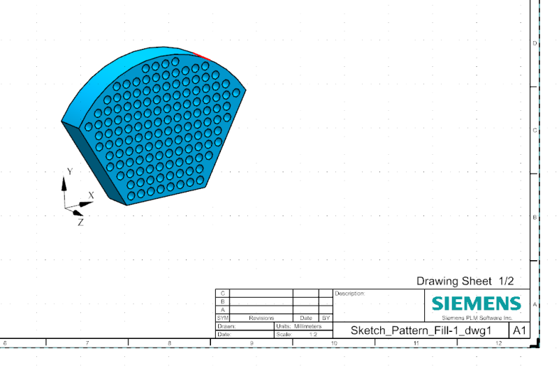
If you add the WCS object to the master part file, when it's displayed in an isometric view on the Drawing, the SYS will also be oriented as in an isometric view as shown below:

WCS_on_Drawing_pbcap9.png


John R. Baker, P.E.
Product 'Evangelist'
Product Engineering Software
Siemens PLM Software Inc.
Digital Factory
Cypress, CA
Siemens PLM:
UG/NX Museum:

To an Engineer, the glass is twice as big as it needs to be.
 
For what it's worth, knowing what all you require up front helps out quite a bit and gets you a solution faster rather than feeding bits of info as we reply.

Now that all that has been taken care of, John's suggestion is more than likely the best for what you're wanting to do....optionally, you could put the CSYS in the dwg file rather than the component to avoid switching between parts and dealing with Reference Sets.

To take care of the CSYS being visible in all views, put the CSYS on a specific layer and utilize Layer Visisble in View to control in which drawing views the CSYS is visible. I don't believe View Dependent Edit will allow you to erase the CSYS (why, I have no clue).

Tim Flater
NX Designer
NX 9.0.3.4 Win7 Pro x64 SP1
Intel Xeon 2.53 GHz 6GB RAM
NVIDIA Quadro 4000 2GB
 
Status
Not open for further replies.

Part and Inventory Search

Sponsor