Continue to Site

Eng-Tips is the largest engineering community on the Internet

Intelligent Work Forums for Engineering Professionals

  • Congratulations SSS148 on being selected by the Eng-Tips community for having the most helpful posts in the forums last week. Way to Go!

coped compression flange of steel beam 1

Status
Not open for further replies.

radiocontrolhead

Structural
Mar 4, 2017
95
Hi All,

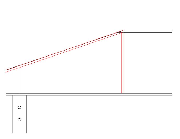
I have a client that wants an open concept and it's forcing me to consider a steel beam to span 30 feet from exterior wall to the other support end.

The problem is that the roof framing will interfere with the beam and it will need to be coped. I have attached a sketch for your review. What are your thoughts? I don't see why it couldn't' work if the numbers checked out and if i could somehow find and effective means of bracing the top edge of the cope web.

the beam depth is 14 inches and the coped height (at the rim block) is 5-1/4"

Thanks all
 
 https://files.engineering.com/getfile.aspx?folder=d51fe7bd-e6f0-405d-80e0-c98724f5a9f7&file=sketch1.pdf
Replies continue below

Recommended for you

OP said:
I don't see why it couldn't' work if the numbers checked out and if i could somehow find and effective means of bracing the top edge of the cope web.

I agree. But, then, everything under the sun works "if the numbers calc out". The trick with something like this is finding a reasonable, yet comprehensive way to check the numbers. No doubt buckling of the top of the web is the thing. The "I don't want to think about this too hard" version is shown below.

c02_mm6g4t.jpg
 
I agree with KootK. Weld on a top flange and a stiffener at the change in top flange angle. "Works structurally and it looks more purty."
 
Agree with suggestion above or similar (running two reinforcing plates at the low part of the web to the vertical stiffener). It looks like a big enough cope that the inverted-T (unreinforced) shape is going to be a little too much for stability.
 
Definitely add the top flange as per kootk sketch. I can't imagine the numbers working out otherwise fir these types of beams with limited bracing along their length.

It's the only way I've ever seen it done round these parts if that gives you some confidence in the solution. Size the stiffener for the component of the flange force changing direction. This vertical internal force acts vertically on the web at the top flange also causing more shear in the end span of the beam. Usually small force though if at the end support where the moment is low, but may need consideration.
 
Radiocontrolhead:
Use Koot’s detail, but add some 2x blocking (both sides) btwn. the new beam (top flg., vert. stiff. & web area) and the adjacent rafters, right up under the roof sheathing. This blocking runs perpendicular to the new stl. bm. and should be nailed to the sheathing, down through the sheathing and into the blocking. This beam must rest on its own stud pack column. What’s the funny two hole tab hanging down from the bm. bot. flg? That should be turned (bent up) 90° to be in the same plane as the bot. flg., so you can screw it down to the top pls. and it can act as a bearing pl.
 
Thank you all,

My client got back pricing for fabricated steel beams (as suggested by KootK) and has decided to move forward with them. I agree completely with all of your suggestions and I thank you for them.

dhengr,

the funny tab is for attachment to a post that will be supporting the beam end. I will detail blocking to prevent rotation at the support as well as along the length of the beam as this will be "upturned" with the top flange unbraced.

The bottom of the ceiling joists will run flush with the bottom of the steel beam so I will use kickers along say 24" o.c. to keep the top flange braced.
 
The end taper may work pretty easily for the reduced moment at the ends, but getting shear to work for that detailing may need a thick webbed W14, which may start to impact your 14" depth.
 
Hi spieng89,

I am sizing W12x35 with a web thickness of 0.27" at the coped end I am hoping to get at least 4-1/2" total depth from t.o.s. to b.o.s. @ support center.

My demand (LRFD) is 10 kips. Capacity based on a phi of 1.0 (per web aspect ratio) is 36 kips. I am detailing as suggested above by KootK to avoid compromising shear strength due to unsupported plate edges.
 
radio - are you still spanning 30'? From eyeball test a W12x35 would be straining to meet deflection limitations if you are seeing 10k at end. If that beam is supporting anything sensitive to deflections e.g. ceiling, mechanical ductwork joints, etc. you may want to double check your deflection criteria
 
Spieng89,

Yes, spanning 30'-0"

It's supporting ceiling and roof. DL of 20, and a roof live load of 20 (reduced to 17 psf) with a trib of 12 feet.

I intend to camber out the dead load about 5/8" but I am finding my deflection criteria is satisfied unless I missed something?
 
If decking is continuously bracing compression flange and with camber, the size makes more sense
 
Status
Not open for further replies.

Part and Inventory Search

Sponsor