Continue to Site

Eng-Tips is the largest engineering community on the Internet

Intelligent Work Forums for Engineering Professionals

  • Congratulations SSS148 on being selected by the Eng-Tips community for having the most helpful posts in the forums last week. Way to Go!

Corbel Details

Status
Not open for further replies.

perfectaccess

Structural
Oct 29, 2015
62
Hi

ACI318-2011

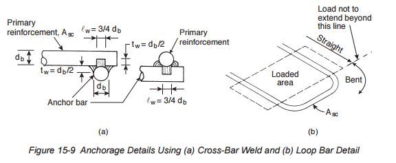
11.8.6 — At front face of bracket or corbel, primary
tension reinforcement shall be anchored by one of the
following:
(a) By a structural weld to a transverse bar of at least
equal size; weld to be designed to develop fy of
primary tension reinforcement;
(b) By bending primary tension reinforcement back
to form a horizontal loop; or
(c) By some other means of positive anchorage.

Can anyone explain a,b options by sketch pls

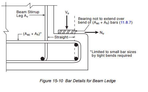
Bearing area on bracket or corbel shall not
project beyond straight portion of primary tension
reinforcement, nor project beyond interior face of
transverse anchor bar (if one is provided).

What I can get from this,that the bearing area should not lies on the concrete cover,while the second part is saying for vertical reinforcement stirrup if exist(the bearing area should not lie outside the vertical reinforcement-->cover area as well)

11.8.3.2 — Design of shear-friction reinforcement,
Avf , to resist Vu shall be in accordance with 11.6.

+Where is the statement in the code deal with direct shear, the code is Tilling to provide as per section 11.6,which I dont understand ,how on the earth parallel stirrups may resist shear,does not make scene?
Where shear-friction reinforcement is
inclined to the shear plane, such that the shear force
produces tension in shear-friction reinforcement, Vn
shall be computed by
Vn = Avf fy (μ sin α + cosα) (11-26)
where α is angle between shear-friction reinforcement
and shear plane.


Finally what is characteristic of this plate bearing,it should be steel,or can i put some high strength plastic material as precast people do,and why use this plate and lieing the whole load on the whole area?
 
Replies continue below

Recommended for you

OP said:
Can anyone explain a,b options by sketch pls

See the sketches below for the a & b options.

Capture_mqhwn3.jpg


OP said:
What I can get from this,that the bearing area should not lies on the concrete cover,while the second part is saying for vertical reinforcement stirrup if exist(the bearing area should not lie outside the vertical reinforcement-->cover area as well)


Close but not exactly right. The first part refers to the left side of the lower bar in the sketch above. The second part is illustrated by the sketch below.

Capture2_lf97nf.jpg


OP said:
b]+Where is the statement in the code deal with direct shear, the code is Tilling to provide as per section 11.6,which I dont understand ,how on the earth parallel stirrups may resist shear,does not make scene?

Direct shear and shear friction are the same thing and are covered in ACI 318-08 11.6.4.

OP said:
Finally what is characteristic of this plate bearing,it should be steel,or can i put some high strength plastic material as precast people do,and why use this plate and lieing the whole load on the whole area?

I like the deformable bearing pads that precast folks use. You get less stress concentration that way and less spalling potential. A bearing plate/pad also helps you keep the load off of the "no-go" zones of the corbel that we've discussed above.

I like to debate structural engineering theory -- a lot. If I challenge you on something, know that I'm doing so because I respect your opinion enough to either change it or adopt it.
 
I agree that Figure 15-9 which KootK provided explains a & b.

The detail in Figure 15-10 does not comply with the requirement of 11.8.6. The bars are not looped horizontally, nor are they welded to the bearing plate as required if a horizontal force (Nu) is present.

Another thing with a ledge as in 15-10...the stirrups must serve a dual purpose, as shear reinforcement and as hanging bars.
 
I assumed in figure 15-10 that headed studs or post installed were to be present on the steel bearing plate but were just omitted for clarity. I doubt they intended for the bearing plate to just sit on top of the concrete without being anchored.

Professional and Structural Engineer (ME, NH)
American Concrete Industries
 
TME,
I assume you mean vertically oriented anchors, which would not provide the anchorage required for the horizontal force. I think that requirement is a "recommendation", as corbel design is not an exact recipe.
 
Really awesome,I learned a lot here.

Still two questions to go
1.I asked before but is not clear why using bearing pads,why not put the whole precast panel on the corbel,in this case they will be more area to carry load and less stress therefore.(sorry I a have a feeling that this dump question,,lol)
2.We all know that indirect shear will be resisted by stirrups,and not all the stirrups will work,my point is usually the crack is 45 degree so your stirrups should be 135 degree(perpendicular) to work efficiently,however people use 90 degree,but we talk about direct shear or direct friction,the concrete will work but how the vertical stirrup parallel to crack will work?90 degree crack+90 degree stirrup?


hokie66


FIGURE 10-15 do agree,because the same statement tell you a third option that i didn't quote, which is any other bending method,which may be vertical loop,besides old version of ACI ,used to mention it before.
 
1. Because you don't want to place the load right on the corner. Rotation of the supported element will cause the corner to crack away.
2. Stirrups don't work parallel to cracks, they work for diagonal tension. They are placed normal to the member for convenience. There was discussion here recently about stirrups placed normal to anticipated cracks, but I won't bother to try to find it. Just do it the standard way.

The "some other means of positive anchorage" doesn't mean just anything will do. There is likely a good reason the ACI code or commentary has been changed.
 
#2) Your usual case with a corbel has your direct shear plane vertical and your shear friction reinforcement horizontal. This orientation works but is sub optimal. The horizontal tie orientation is chosen for constructability. For normally proportioned corbels, there's really no such thing as a diagonal tension mode of shear failure. The applied load is brought down to the supporting structure via a diagonal compression strut. I've always found the shear friction check to be an odd feature of corbel design. With a strut and tie based design, there would theoretically be no need for shear friction. Belt and suspenders I suppose.

I like to debate structural engineering theory -- a lot. If I challenge you on something, know that I'm doing so because I respect your opinion enough to either change it or adopt it.
 
Kootk,

My understanding has always been that shear friction is an ACI simplified calculation method (empirical) to try to satisfy a strut and tie solution. You use one or the other, not both!

And you can still get a diagonal tension crack perpendicular to the compression strut in the strut tie solution! This is normally ignored for small continuous seat type corbels but should be considered in dapped ends on precast beams, etc where the loads and stresses are more substantial.
 
rapt said:
My understanding has always been that shear friction is an ACI simplified calculation method (empirical) to try to satisfy a strut and tie solution. You use one or the other, not both!

Yes, that is my understanding as well. Additional thoughts:

1) As Hokie mentioned, it's not an exact science. I wouldn't fault anyone some redundant conservatism.

2) I believe that the ACI simplified method has been corroborated via testing which lends it some credibility in my estimation.

3) Often, I like the results of the ACI simplified method better than strut and tie results.

4) If you didn't have shear friction bars you'd probably have similar reinforcement as strut and tie crack control bars. Six of one, half a dozen of the other.

rapt said:
And you can still get a diagonal tension crack perpendicular to the compression strut in the strut tie solution!

Sure, it's just not a crack that would result in a shear failure or that we'd reinforce for explicitly other than crack control.

I like to debate structural engineering theory -- a lot. If I challenge you on something, know that I'm doing so because I respect your opinion enough to either change it or adopt it.
 
Status
Not open for further replies.

Part and Inventory Search

Sponsor