Continue to Site

Eng-Tips is the largest engineering community on the Internet

Intelligent Work Forums for Engineering Professionals

  • Congratulations waross on being selected by the Eng-Tips community for having the most helpful posts in the forums last week. Way to Go!

Corner cracking in Bump testing

Status
Not open for further replies.

GarethMcGrory

Mechanical
Jun 26, 2013
16
Hello all,

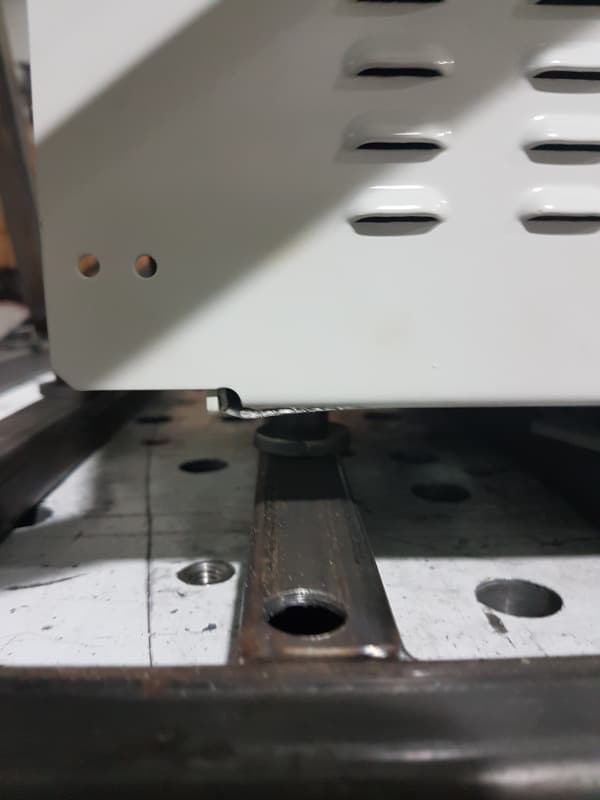
During recent testing of an electronic chassis, the corners at the floor are suffering cracking as show in attached photo.

Initially there was no corner relief in the design, which I changed to have corner relief. Picture attached also to show the area which is showing cracking. However even with the corner relief, cracking has occurred.

The failure is happening in the up/down axis of bump.

I am thinking of welding the seam fully to prevent this.

Questions:
1. will welding the seams fully, be sufficient?
2. Is it likely some internal bracing is required to prevent any cracking?
3. Any other suggestions as to a simple solution to my problem?


Alll ideas welcomed, thanks for taking time to read


Regards
Gareth


 https://files.engineering.com/getfile.aspx?folder=6040004d-5735-4298-8c5e-87f40be9ae62&file=20181116_183948.jpg
Replies continue below

Recommended for you

I may not follow exactly which direction is being bumped, but I would ask the following questions:

1) Does changing the bend radius affect the tear that is occurring on the corner that has the brake?
2) Is the material suitable for the current bend radius?
3) Does the material have a tendency for significant work hardening when you brake the corner? i.e., is it too hard to begin with and/or do you want to use a material that has been annealed to reduce the crack propagation?

Engineering is not the science behind building. It is the science behind not building.
 
Gareth,
To help yourself get answers, attach the photo so that everyone can see it, instead of forcing everyone download.
20181116_183948_sdodyq.jpg


Assuming that the bend wasn't cracked to begin with (see EngineerTex's comments)...
If your box is built the way I think it is, you need to attach the flange behind the wall to the wall in the picture. The already come together, so they can mutually support each other if they can be attached together. It doesn't have to be welded, but that's a possibility. Another way is to rivet or spot-weld an angle between the two faces.

No one believes the theory except the one who developed it. Everyone believes the experiment except the one who ran it.
STF
 
Tex, the material is suitable for the bend radius applied, which is a typical bend radius used as required. I will however double check this as suggested.

Sparweb, I am having similar thoughts as to how to strengthen the structure in this area. At present i am proposing to weld the seam and add an L angle along a part of the length assuming i have clearance on the interior to do so.


Could strength be added by welding a large fillet on the interior along the bend line. i.e. localised thickening of the material. Or would this be a not recommended practice?

Thanks for replies so far guys, appreciated


regards
Gareth
 
At the small end of the bend radius limit, most of the metal will be near the tensile limit, leaving little for further deformation. The problem isn't a strength problem, it's an energy absorption problem, which will be divided between damaging the item and elastic (spring) deformation. The stronger you make this area, the higher the loads will be.

The best strategy is to determine how much energy needs to be dealt with and then decide where it should go. That decision may be affected by how much acceleration things inside the box can withstand.
 
To echo Dave, it may be too strong already. You may need to add weld to hold the joint together, but remove some metal so that it bends and crumples instead of breaking.

= = = = = = = = = = = = = = = = = = = =
P.E. Metallurgy, Plymouth Tube
 
GarethMcGrory said:
Tex, the material is suitable for the bend radius applied...

3DDave and I are both getting at a suggestion of making the bend radius larger, even if the current radius is fine for the brake operation that forms the corner. The current radius may not be fine for the brake operation plus an impact load.

A larger bend radius may be the simplest method of redesign that requires the minimum amount of change to your current setup.

Also, how is the chassis loaded, restrained and then bumped when you are performing this test?

Engineering is not the science behind building. It is the science behind not building.
 
Load path and stiffness.

Load comes in on the foot. Where do you want it to go?

How can it get there without exceeding yield strength of material along the way?
 
Try cutting off that little white square of sheet metal next to the tear. It is hitting the metal above during your test and acting as a crow bar to tear the sheet metal.


Compositepro,
That "white square" is actually the lower edge of a vertical flange which may be an entire wall panel on the side we can't see for the box wall we are facing in the photo view.
That flange should be attached to the forward wall, so that they can work together and mutually reinforce the corner in terms of both strength and stiffness.
Of course, the previous comments about tight bend radius also still stand...

Gareth,
Thick weld? No that will just warp the panels. If you have ready access to welding equipment, I'd suggest a weld bead 1/2 thickness of the base material. Otherwise you can add an angle part and rivet/spot weld it to the corner of both panels, and it will make an even stiffer corner joint. Whether that's adequate or not is anyone's guess without much more information about the enclosure, what it's for, what the box weighs, etc.... No suggestions can be realistic or practical if you don't provide detailed information about the material type, thickness, temper, flange sizes, method & radius of bending, etc. etc. etc...

Actually I figure you have enough suggestions to solve this one already, but do please let us know what works, when you do. Good luck!


No one believes the theory except the one who developed it. Everyone believes the experiment except the one who ran it.
STF
 
Gareth,
Thick weld? No that will just warp the panels. If you have ready access to welding equipment, I'd suggest a weld bead 1/2 thickness of the base material. Otherwise you can add an angle part and rivet/spot weld it to the corner of both panels, and it will make an even stiffer corner joint. Whether that's adequate or not is anyone's guess without much more information about the enclosure, what it's for, what the box weighs, etc.... No suggestions can be realistic or practical if you don't provide detailed information about the material type, thickness, temper, flange sizes, method & radius of bending, etc. etc. etc...

Actually I figure you have enough suggestions to solve this one already, but do please let us know what works, when you do. Good luck!


Hi Guys, thanks for all input so far. Unfortunately this was a design we inherited, & the vibration testing is a higher specification (more severe) than anything the chassis ever passed in previous lifetimes.

1. The enclosure houses an array of large PCBS which are complex equipment used in the Electrical utility industry.
2. This is standard 6U size chassis
3. Historically the steel material is specified as 'MILD STEEL', not very specific i know. I have requested material data sheet of the actual material used, awaiting response
4. The Chassis is mounted to the Vibration frame using Aluminium Alloy 6061 T6 L-Angle brackets
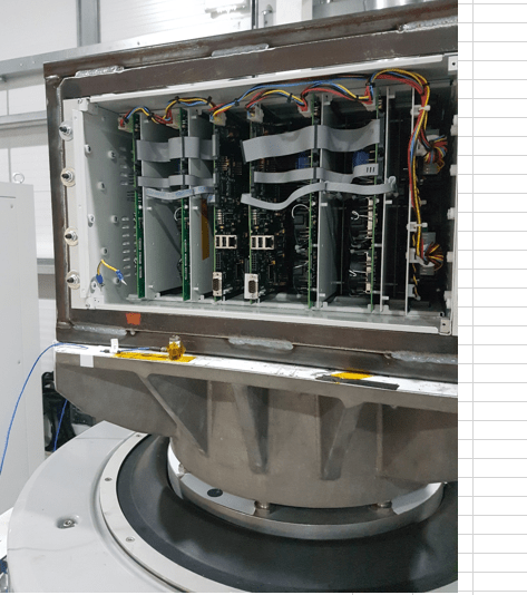
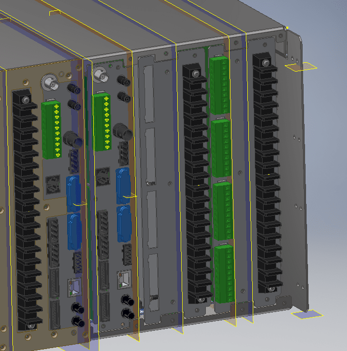
5. The chassis is mounted so as to simulate mounting in a cabinet. Therefore it only is held at the front through the 8off M6 bolts. The back is hanging in free space.
6. The chassis base which is a U-shaped fold, with some small fold up tabs at the rear (to mount rear panels is 1.6mm thickness. Bend radii for example on this piece are equal to material thickness, 1.6mm.
7. The roof is then a smaller U-shape which is bolted to the chassis base.

The total mass of the unit is approx 24 kilograms, a monstrous mass to enter the vibration testing specified:


Full Mechanical Test Suite definition
a. Vibration response IEC 60255-1 (IEC 60255-21-1)
b. Vibration endurance IEC 60255-1 (IEC 60255-21-1)
c. Shock response IEC 60255-1 (IEC 60255-21-2)
d. Shock withstand IEC 60255-1 (IEC 60255-21-2)
e. Bump IEC 60255-1 (IEC 60255-21-2)
f. ~4-hours for all 5 tests on 1-axis, so ~12-hours for a complete range of 5-tests across 3-axes.

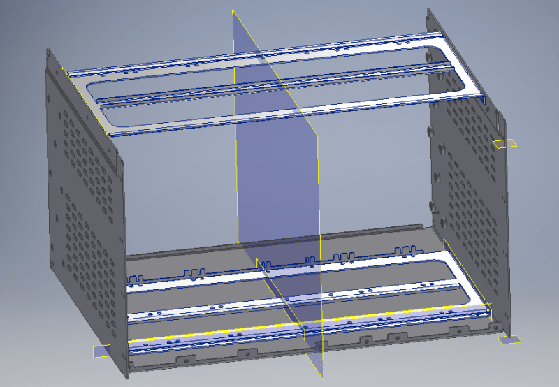
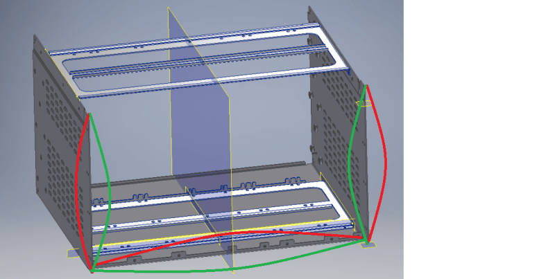
Hopefully this uploads ok, an image of the rear of the chassis from the 3D model. No roof or rear plates shown for clarity.

Chassis_rear_base_frame_only_cesqgw.png


Front of chassis showing mounting within the Vibration table frame. Held at front only through use of 8off M6 bolts.

Front_of_chassis_mounted_on_shaker_table_afkgk7.png
 
Seems pretty likely that your side and bottom panels are doing something like this:

deflection_j5dnyf.png
 
Forget welding. The bend radius is too small for the material, which appears to be aluminum. If tempered, do the bends at T0 or T1 and let age to strength.Strength is not likely an issue here since it is just an enclosure.
 
Ron, the material of the chassis base is 1.6mm thick Zinc plated mild steel. The inner bend radius is equal to the material thickness in this instance.

Also see above for the conditions, this is a 24kg enclosure enduring extreme vibration, shock & bump.
 
Gareth..thanks for the clarification. My bad!
 
Knowing more about the specifics - this is a frequent problem where there is an abrupt change in stiffness. It serves as a stress concentration and a place to initiate a crack. The usual answer is to add a doubler plate to stiffen the weaker item and transition the load from there to the stiffer part. The reason for the change in stiffness is the flange that has no matching structure, making it effectively infinitely more stiff than the bottom surface which has no material at that location. As it is, it is designed like a 'tear here' feature. If you've ever pulled a sheet of paper over the corner of a table to tear it, you've done what this is doing.

In other, similar situations, I have seen people add local structure which merely serves to move the discontinuity elsewhere, and with it, the cracking. It's best to get an FEA model that correctly represents the juncture to decrease the number of tests. I would start with a 90 degree bent bar about 2X thickness and 8:1 W:t ratio that extends 30t along each face and heavily spot welded or riveted to spread the load. I think that won't be the final answer but it's an analysis start.
 
Can you show the rear and roof plates? As @SparWeb mentions a couple of times above, I think that you need to look at how the floor is connected to the side walls. Is the rear plate connected via fasteners to *both* the floor and the wall? If the back wall is not connected to the side wall and the floor (assuming that the floor is where the electronic cards are mounted), that may be the cause of the cracking.

Engineering is not the science behind building. It is the science behind not building.
 
Hi Tex,

Sorry for the delay in reply. Rear plate is connected to roof and U-shaped chassis base using screw fasteners.

Capture_w9onql.png


Due to time constraint on a test slot which was already booked, I have introduced L-Shaped stiffening brackets in internal corners. I will provide an update when test complete to see if this is sufficient to stop floor tearing.
 
Status
Not open for further replies.

Part and Inventory Search

Sponsor