Continue to Site

Eng-Tips is the largest engineering community on the Internet

Intelligent Work Forums for Engineering Professionals

  • Congratulations Danlap on being selected by the Eng-Tips community for having the most helpful posts in the forums last week. Way to Go!

Corner Joint Efficiency - UW-12 1

MchA

Mechanical
Dec 5, 2023
17
Dear all,

I am currently designing a hairpin heat exchanger under ASME VIII-1 Ed. 2023 with the following design conditions:
  • Corrosion Allowance: 1.6 mm
  • Shell Side Pressure: 10 barg, Temperature: 280°C
  • Tube Side Pressure: 93 barg, Temperature: 280°C
  • Joint Efficiency Required by Client: FULL
The design includes a corner joint as per Fig. UW-13.2(m), classified as Type No. 7 in Table UW-12. I understand that:
  • This type of joint, under UG-34, might be considered with a joint efficiency of 1.0 for design purposes (i.e., no joint efficiency is required, see interpretation below, despite a factor E, joint efficiency is taken into account in the required thickness calculation).
  • If all requirements of UW-13(e) are met, and all inspections under UG-93(d) are performed, could this joint be effectively assigned a joint efficiency of 1.0, thus allowing us to categorize the nameplate joint efficiency and extension of radiograpy as RT1 or RT2 (even though these joints cannot be radiographed)
Additionally:
  • If the joint efficiency is capped at a lower value (e.g., 0.85), would this require the overall equipment to default to RT3, thus excluding RT1 or RT2?
  • If the equipment defaults to RT3, would this require changes to the design calculations to match the radiographic category and ensure compliance?
I consulted a NOBO regarding the weld joint efficiency for corner joints (like Fig. UW-13.2(m) or UW-13.2(c)), and this was their response:
  • Weld joint efficiency applies only to components designed with the design by formulas method, particularly membranes of revolution (e.g., shells or heads).
  • Other components, like air-cooled or flat heat exchangers, do not require a joint efficiency.
  • For corner joints meeting the dimensional and construction requirements of UW-13(2), the joint is considered structurally adequate without needing a weld efficiency factor.
Considering this, I presume I might consider the joint efficiency as 1, but the ASME Inspector disagrees with this view and confirms that under ASME VIII-1, the joint efficiency for corner joints must be SPOT.

Moreover, a joint efficiency lower than the effective control could be dangerous and impact the integrity of the design. Therefore, I would like to clarify if such an approach can be accepted or if it will require further adjustments.

Additionally, I referred to the following ASME Interpretations for further clarification:
  • Interpretation VIII-80-117: There are no criteria in Section VIII - Division 1 for establishing joint efficiencies for corner joint attachments; only the C and ZC factors are required to determine the required thickness of the flat plate in UG-34. The NDE requirement is specified by the provisions outlined in UG-93(d)(3) and UW-13(e), and the requirements for fillet welds as given in UW-36. Moreover, f full radiographic examinations or equivalent of the longitudinal shell joints in a vessel are to be undertaken for whatever reasons, are corner joints according to Fig. UW-13.2 still allowable or must one of the constructions allowing full radiography as per Fig. UW-13.2 be adopted? Reply: Corner joints would be allowed.
  • Interpretation VIII-1-04-46: Question (1): Is it required by the rules of Section VIII, Division 1 for welded joints as per Fig. UW-13.2, sketches (m) and need to be examined by full radiography or spot radiography when the vessel in which these corner joints are included is subject to the full radiography requirements of UW-11?
    Reply (1): No.
  • Interpretation VIII-1-89-227: Assuming no radiographic examination is required by the Code, would any radiographic examination of this corner joint affect the joint efficiency used in calculating the required thickness for the seamless shell under internal pressure? Reply (1): No.
    Question (2): With no radiography of this corner joint, would the joint efficiency of the seamless shell used in calculatio ns be E = 1? Reply (2): Yes.
    Question (3): Would the requirements of UW-11(a)(5)(b) ever need to be met for the corner joint described above? Reply (3): No.

Thank you for your guidance!
 
Last edited:
Replies continue below

Recommended for you

but the ASME Inspector disagrees with this view and confirms that under ASME VIII-1, the joint efficiency for corner joints must be SPOT.
See UW-11(a)(4) and UW-11(a)(5)(-b).

  • Shell Side Pressure: 10 barg, Temperature: 280°C
  • Tube Side Pressure: 93 barg, Temperature: 280°C
  • Joint Efficiency Required by Client: FULL
Your tube side pressure is quite high. Are you still really using a corner joint rather than a butt weld on your tube side with that heavy plate thickness and temperature?
Are you using typical hairpin configuration per API663 or would it look something like an NEU type heat exchanger?
 
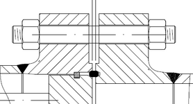
Thank you, R6155. This is the sketch. The weld I am referring to is the one connecting the shell nozzle to the flat cover on the right side

See UW-11(a)(4) and UW-11(a)(5)(-b).
Thank you, Trestala! I now understand that I have a Category C joint, which is not required to be radiographed because there is no intersection with a Category A joint. Furthermore, since this joint cannot be radiographed, according to Table UW-12, I can still use a joint efficiency of 1.0.

Regarding radiographic requirements, I cannot be classified under RT-1 because my joint is not fully radiographed. As a result, I would fall under RT-3 or RT-4, where spot radiography is required.
These thoughts might be extended also to air-cooled corned joint, am I right??
Your tube side pressure is quite high. Are you still really using a corner joint rather than a butt weld on your tube side with that heavy plate thickness and temperature?
Are you using typical hairpin configuration per API663 or would it look something like an NEU type heat exchanger?
Given the tough tube side design conditions, we’re weighing the pros and cons of an API 663 Ed.2022 Separated Head Front Closure versus a Typical Standard Front Closure. While the Separated Head offers benefits for managing high temperature differences and thermal expansion, it also brings added complexity and the risk of leakage from multiple flanges. Since our tubesheet isn’t very thick (around 80mm for a 14” shell), we’re leaning towards the Standard Front Closure, which simplifies the design, reduces leakage points, and makes maintenance easier, even if it’s less flexible for extreme temperature gradients.

What are your thoughts on this? Have you worked with either configuration in similar applications? Any experiences or insights would be really helpful!


Attachments

  • Sketch.jpg
    Sketch.jpg
    77.4 KB · Views: 13
Regarding radiographic requirements, I cannot be classified under RT-1 because my joint is not fully radiographed. As a result, I would fall under RT-3 or RT-4, where spot radiography is required.
These thoughts might be extended also to air-cooled corned joint, am I right??
It can still be classified as RT-1 & RT-2 even if you do not perform RT on the Cat C joint per UG-116(e)(1) & (2) as long as within the UW-11(a) rules.

we’re leaning towards the Standard Front Closure, which simplifies the design, reduces leakage points, and makes maintenance easier, even if it’s less flexible for extreme temperature gradients.
If you're within API 663, 7.5.2., you can go with typical front closure. However, some Owners do still apply the Separated Head Front Closure if you're above pressures of 300# flange class to separate the SS and TS bolting.

What are your thoughts on this? Have you worked with either configuration in similar applications? Any experiences or insights would be really helpful!
I would probably look first into rerating your STHE so you can go with TEMA/API 660 configuration. But API 663 should still be fine.
 
Please, send us the actual design detail drawing with the tubesheet.
 

Thank you so much Trestala!


Please, send us the actual design detail drawing with the tubesheet.
1738955604666.png
This is the flange with split ring, ring joint and tubesheet. In this case the RT can be done on the flange welding, but in the rear closure, as shown before, we would have a corner joint so no RT can be done.


Note 8, Table UW-12.
Thank you, David. I noticed Note 8 in Table UW-12, but I was aware that using a joint efficiency lower than the effective control could be dangerous, despite these kind of joints don't need a RT-control.
Moreover, it’s still not entirely clear with the ASME Inspector whether I can have a global joint efficiency of 1.0 for the vessel while using RT-3 or RT-4 as an extension of radiography. As long as RT-3 and RT-4 are partial inspections, I’m questioning whether these partial inspections are sufficient to justify a full efficiency of 1.0 for the entire vessel, especially considering safety and design integrity, under UW-12, UG-116 and UW-11.
 
Last edited:
You can't have E=1 with RT-3 as the whole vessel is spot. RT-4 is an umbrella term for any RT that doesn't fall into RT-1, RT-2 or RT-3. You can certainly have E=1 with RT-4 for circumferential stress and head thickness.
I wouldn't call RT-4 partial inspection either....it could be RT-2 which is considered full radiography, but add another spot on the circ and it becomes RT-4, but actually has more RT completed.
It sounds like you are putting the cart before the horse. Figure out what amount of nde you are doing then see which Category (RT-1/RT-2 etc.) it falls into.
 

Part and Inventory Search

Sponsor