Eng-Tips is the largest engineering community on the Internet

Intelligent Work Forums for Engineering Professionals

Correct method for tolerancing parallelism from a datum (ASME Y14.5)

Status
Not open for further replies.

mackra

Mechanical
Sep 7, 2011
16
0
1
US
ASME Y14.5

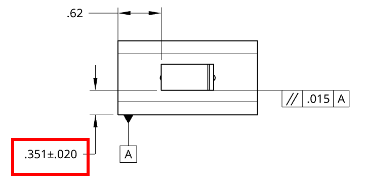
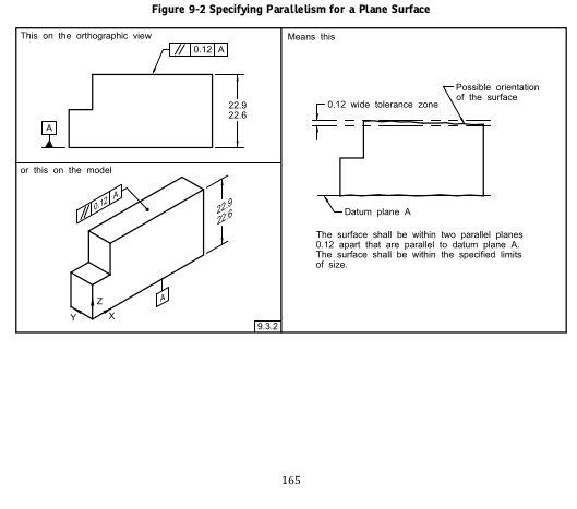
At my work, we don't use GD&T much, nor do I. I'm creating an assy drawing and specifying alignment (parallelism) of one part to another. The two images are sort of representing what I'm wanting to accomplish. Which of the two images below correctly dimension the .351 distance? I'm getting feedback that the first image (Option 1) is double dimensioned and it must be a basic dimension (Option 2). However I disagree as the Figure 9-2 in ASME14.5-2018 shows something similar and is not a basic dimension.

Option 1 Drawing as submitted and rejected
2024-04-03_18-51_iwrgyz.png


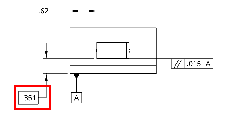
Option 2 Drawing as what's being stated is "correct"
2024-04-03_18-56_ywduvv.png


AMSE Example
2024-04-03_19-05_a2h1rz.png


I have yet to find an example using Option 2.
 
Replies continue below

Recommended for you

Short answer: unless there is a general profile tolerance in the notes, option 1 is correct.

Longer answer: parallelism is an orientation tolerance, and not a location tolerance. Therefore, it can't locate the flat .351 from datum A. You need some location tolerance (coordinate or geometric) to locate the flat. Unless you use profile to locate the surface or position to locate the center plane, a basic dimension is incorrect.
 
The standards appear to not have any "don't do this" examples and only sparse examples of the possible "this is what works."

Many on-line resources also, honestly, suck. While Profile of surface can serve to locate where a surface is relative to the datum reference frame, the first 5 hits said it just controls the "profile" which is an entirely useless circular definition.

You could write a note that says "variation in the distance from this surface (with a label) to a flat surface held against that surface (maybe with a label) shall be in a range of 0.015" to control parallelism

You are still stuck with defining the envelope principal to set the form limitations on both surfaces at the maximum amount of material, so maybe just getting a copy of the standard and reading it is a better idea.

I wouldn't say its the best $250 you may spend on a book, but for $700 you can get it and some online training. I doubt it will contain any "don't do this" examples, but it's been a while since I looked all through it.

The 1 year access $700 online training also gets access to "An e-copy of the 400-page GeoTol Pro 2020 book by Scott Neumann and Al Neumann, which contains full color graphics and loaded with student exercises. (Access for the duration of the course)"
 
I agree with the others, but I would also like to point out the following:
If the .351+/-.020 dimension is intended to control the location of the surface (to which parallelism is applied), a better practice would be to make the dimension basic and apply a profile tolerance of .040 relative to datum A to the same surface, placing the profile of a surface feature control frame above the parallelism callout. The reason for this is that the plus-minus toleranced dimension is controlling size - which means distances between opposed points, and the form of both opposed surfaces depending on the amount of departure from maximum material condition. If you would prefer to control location from a datum, replacing the directly toleranced dimension with a basic dimension and a profile of a surface tolerance would be the right choice.
 
Since this is an assembly drawing, I am going to assume the two faces of the .351 dimension are not opposed to each other. If that's correct assumption, then Y14.5-2018 explains why making it a regular +/- dimension is not recommended option (see Appendix I).

Making the dimension basic and applying a profile tolerance relative to A in addition to the existing parallelism callout would be the cleanest way. See fig. 6-30 in the 2018.

Alternatively, if whoever that is going to consume the drawing has allergy to profile tolerancing, the origin symbol may be used to replace the arrowhead at the bottom end of the dimension line and the dimension may remain +/-.
 
If it is the case this is a box on top of another box, the top/mating surface probably should be the primary datum feature reference and the secondary datum feature reference should be a very limited datum target area near that primary datum surface to prevent the problems that projecting the side surface can cause if it is not perfectly perpendicular to the top surface. It may also be worthwhile to make the controlled surface on the smaller box a small area rather than the entire face for a similar reason.

However, as in the other 99% of these questions, there needs to be more than some desire to make this control because something needs to be controlled. There needs to be an analysis of what the functional limits there are to the requirement before any control can be selected or tolerance applied.
 
Since we don't know the height of the boxes, it's hard to tell if this could cause any significant problem and if defining small areas on both boxes would add a value. Making the mating face primary for the parallelism callout (it then would have to become perpendicularity, of course) would also require some caution as the perpendicularity tolerance value at the assembly level could not be smaller than at the piecepart level.

Since per the OP they don't use GD&T much, maybe the direction should be to clarify in the note that the +/- dimension shown in the view applies at the mating face only (to avoid the 3D orientation effects) and that its measured values shall not vary more than .015 between its both ends? Still not a perfect solution but at least prevents from overloading the drawing with a bunch of GD&T callouts and supplementary annotation that may simply end up being too much for the intended functional requirement and too complex for people not used to work with GD&T on a daily basis.
 
Or it could be the small areas is absolutely the best thing since sliced bread. Maybe wait for the OP to tell what the totality of the problem is. Put a dial indicator on a sled that overhangs just a bit and set it to the height specified it is solved rather than putting it onto a granite slab on a CMM. Instead of parallelism - use the lower segment to a composite profile.

---

"dimension shown in the view applies at the mating face only (to avoid the 3D orientation effects)" is exactly what the value of defining small areas is for. Since there may be a small radius discovering where the "edge" is is problematic.

The "origin" symbol has at least as many problems.
 
Status
Not open for further replies.
Back
Top