Eng-Tips is the largest engineering community on the Internet

Intelligent Work Forums for Engineering Professionals

Could this load cause line notching? 5

Status
Not open for further replies.

123MB

Electrical
Apr 25, 2008
265
0
0
AU
Hi All

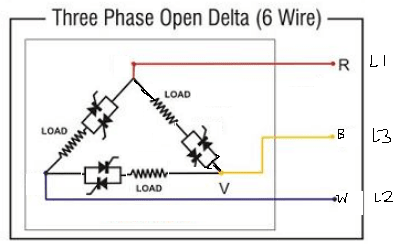
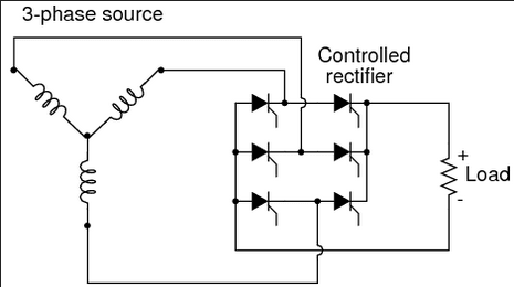
We have a SCR/Thyristor heating system with a configuration shown in the attachment. The device is a phase angle controlled resistive Silicon Carbide heating controller

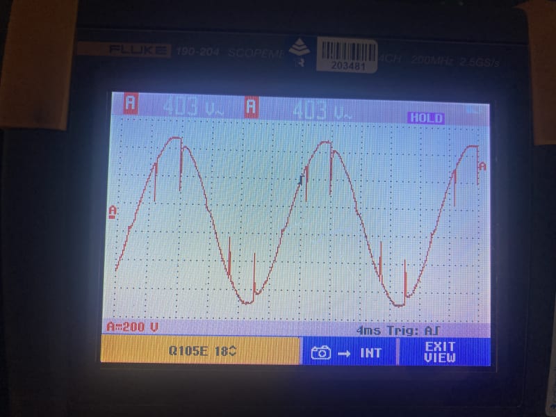
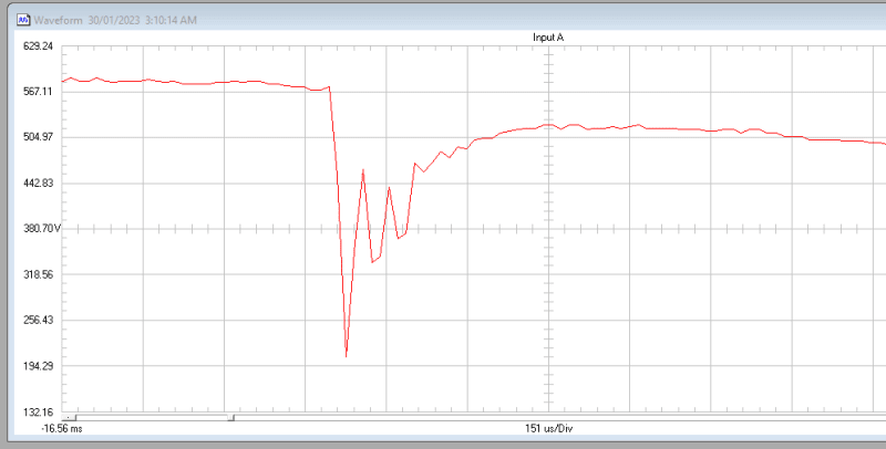
We are seeing possible signs of line notching being caused by the controller - is this possible? I thought that line notching would only be caused by converters producing smooth DC - I do not see how the converter per the figure shown could cause a phase to phase short i.e. leading to line notching...

Although maybe I am missing something? Perhaps if the load resistance was low enough it could present a short due to some commutation overlap?

Any comments? Cheers


 https://files.engineering.com/getfile.aspx?folder=12fe6936-e532-4c8d-92cc-ae1f13dd4017&file=2023-01-24_10_20_33-heater-power-controller.pdf.png
Replies continue below

Recommended for you

In a phase angle control scheme, yes, it can (will) cause line notching. That's exactly the down side of using phase angle control (as opposed to zero cross variable time base control).


" We are all here on earth to help others; what on earth the others are here for I don't know." -- W. H. Auden
 
Hi Jraef, thankyou for your reply.

Are you able to please help me understand? I feel like I have thought about this in and out and I cannot conceive of how this is occurring. I understand how it could occur on a fully controlled rectifier bridge, but I can't see how that applies in this case, as the load (heating elements) are always in the circuit and hence a phase to phase short never occurs
 
It has to do with how phase angle control is accomplished with SCRs. If you only look at one SCR is seems simple enough in that you gate it On, then it turns off at the next zero cross. But to make phase angle control function, you must turn on TWO SCRs in separate phases, then there is a 3rd phase that will be gating before the others are done. So for a brief moment in each cycle (sometimes only microseconds), there are minor short circuits as you have multiple commutation overlaps at the same time.


" We are all here on earth to help others; what on earth the others are here for I don't know." -- W. H. Auden
 
Thanks jraef,

I can't for the life of me understand it. Even if all six of the thyristors are on simultaneously I do not see how a phase to phase short circuit could be caused, not in the same way as if the thyristors were connected in a bridge.

What about a typical soft starter as an analogy, I have never seen any commutation overlap type notch being introduced by those devices.

Sorry mate there is something about this I am not getting - you should see the number of sketches I have done trying to get this straight! [bigsmile]
 
No, the devices can't cause line to line shorts.

The heating elements could be a very low resistance until current is flowing causing a transient current when a SCR turns on.
 
Cross firing (improper commutation) initiated by power supply upsets is possible in some older SCR/Thyristor power supplies. In my limited experience this almost always results in blown SCR protection fuses inside the power supply.
 
This isn't a power supply though, it's a 3-phase controller. You can fire the SCRs any way you want and there will never be a phase to phase SCR short.
 
Lionel
The equipment I was referring to is a now long retired SCR drive for a several hundred HP DC crane hoist. The upset was across the line starting of a 1000+ HP motor which was on the same MV circuit. It was the distorted waveform tat would some times create a situation where an SCR would not commute off as the zero crossing occurred late, after the an SCR on a different phase gated on.
Yes I know this is not supposed to be the way SCR;s work, and we need to be careful about incompatible loads. Sometimes us facilities engineers need to live with others less than Ideal decisions for a while.[hammer]
Result - sort of a 3 phase bolted fault inside the drive. At least enough current to usually blow the drive fuses, which most of the time protected the scr's
Screenshot_from_2023-01-30_19-42-01_bmqumj.png
 
Update on this guys, I checked the system out with a scope meter and I have attached an example of the rather alarming waveforms which were present.
IMG_5766r_zseqsl.jpg


The measurement was phase to phase on a sub circuit which is fed from the main board in the facility - not on the actual SCR controller feeder - hence what you are seeing here is the voltage at the main switchboard i.e. right on the transformer secondary - hence this voltage is seen by the rest of the facility.

At this point I am lost as to the cause. My best ideas:

1) the load is resistive, so even though there's high DV/DT when the thyristor turns on, I wouldn't expect any inrush - unless there are significant parasitic capacitances or inductances at play which are interacting with the fast DV/DT and causing a current surge which is pulling the voltage down. There's potential for some parasitic capacitances in the load but nothing dramatic. It's worth noting that this is not a stiff source and there isn't much inductive reactance upstream of the SCR controller.

2) the load is heating elements with about 0.6 ohm resistance per phase at the furnace operating temperature (for new elements) and the RMS current draw is in line with this - but the condition shown is not a function of the element heat up etc as it occurs at steady state.

See below close up of one of the 'notches'

2023-01-31_12_47_13-FlukeView_ScopeMeter_-_LARGEF_1.FVF_dik68q.png
 
FacEngrPE - Sure, but that's not the configuration the OP posted a diagram of, and in his diagram the SCRs can't cause phase to phase shorts. I just looked at it again and it looks wrong though.

123MB - You initial diagram shows the SCRs connected to U from two of the heater loads. That doesn't look right. The SCRs should be at the same end of each load going around the delta. In other words, between U and W and the SCRs should be connected at the W end. Check the configuration and see if that diagram is correct or is not representative of your system.


My mistake, If the wiring diagram is correct, the lowest possible resistance should be the heater, not the kind of low resistance that would cause that large of a notch.
 
The transient voltage could be triggered by the sudden increase in current flowing through inductance and stray capacitance. It appears to be a damped high frequency ringing.
 
Thanks jghrist. I am starting to think it's mostly about the source not being very stiff, having a relatively high secondary impedance and the very high di/dt at thyristor turn on is causing the voltage dip of the source. Perhaps there's also some capacitance and the like interacting with it. I do not have the numbers with me at the moment to calculate a potential notch depth assuming inductive voltage drop is the cause.
 
Status
Not open for further replies.
Back
Top