Eng-Tips is the largest engineering community on the Internet

Intelligent Work Forums for Engineering Professionals

Coulomb's Damping Equation for Machine Vibration 3

Status
Not open for further replies.

m_ridzon

Mechanical
Sep 18, 2020
68
0
0
US
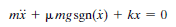
I am working on a large industrial machine on frictional skid rails (i.e., 1 dimension of movement is possible on the rails). As its motor starts up, it begins to vibrate the machine around 20Hz; i.e., movement occurs on the frictional rails. The phenomenon is similar to what is shown in the YouTube video HERE. This is quite similar to Coulomb's damping scenario (images below).
Coulombs_1_cxmt4q.png
Coulombs_2_rg0wvp.png


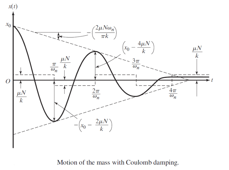
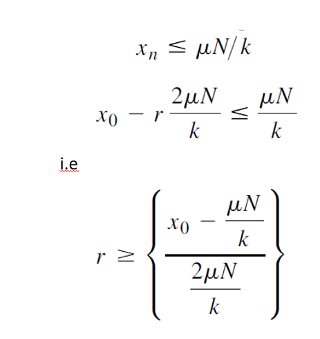
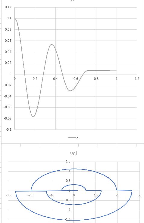
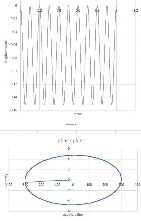
"r" is the number of half cycles that elapse before motion ceases. However, the equation assumes a spring participates in the situation (hence the variable "k"). It also assumes there is an initial displacement, x[sub]0[/sub] applied to the assembly. Neither the spring, nor the initial displacement occur in my scenario. Does anyone know how or if Coulomb's equation is modified to account for my scenario?

(note: yes, I understand an imbalance in the rotating assembly is likely the cause of the vibration and should be looked at. However, for all intents and purposes, we can assume in this conversation that the source of the vibration is there to stay. The structure and its motor are huge. So even a tiny imbalance may lead to large energy addition to the structure. With a free DOF along the skids, the energy may be enough to excite movement.)
 
Replies continue below

Recommended for you

Does the excessive/notable vibration cease when the machine is up to speed?
So the "large industrial machine" has it's rotating shafts oriented perpendicular to the rails?
And there are no wheels contacting the rails. Just skids?

Is the "vibration" accompanied by rigid body motion of the " large industrial machine" sliding/skidding along the rails,

A few picture of the arrangement would be at least as helpful as the lack of pictures is confusing.
 
My apologies, as I only have limited information at the moment. So I'll do my best to answer the questions...

tmoose said:
Does the excessive/notable vibration cease when the machine is up to speed?
I believe 60Hz is full speed. It was explained to me that 20Hz is a problem, but I cannot say for sure if it disappears above 20Hz.

tmoose said:
So the "large industrial machine" has it's rotating shafts oriented perpendicular to the rails?
I'm not sure. That information hasn't been disclosed.

tmoose said:
And there are no wheels contacting the rails. Just skids?
Only skids. No wheels. You can imagine a ski on snow, except this is metal on metal.

tmoose said:
Is the "vibration" accompanied by rigid body motion of the " large industrial machine" sliding/skidding along the rails
Yes, it is similar to the YouTube video I shared. It moves rather violently in the direction of the skid rails.

tmoose said:
A few picture of the arrangement would be at least as helpful as the lack of pictures is confusing.
I agree, but unfortunately I do not have them at the moment. The machine was shown to me, but I was not given photos to share.

Bottom line, I think FEA will be needed to simulate this, but I had hoped to get something meaningful with a hand calc of Coulomb's. If that's not possible, then I'll just revert to FEA.
 
m_ridzon,

Let's be practical here.

That shop floor is not level. It is tilted downward and to the right, which is why the vibrating machine moves in that direction.

I figure the rubber mat does two things. It acts as a vibration isolator between the metal base and the floor. There is no clattering of the legs against the floor. If the vibration acceleration is well below 1G, there is lots of friction contact between the floor and the three[‑]legged base, so that it can't move.

Your vibration isolator reduces the vibration displacement and force transmitted to the floor. Effectively, it is providing a degree of freedom to the base and grinder above. The rubber mat increases the vibration movement of the grinder.

Vibration happens because you have mass, spring(s), and one or more forcing systems. Most of your springs could be your vibration isolators. If the forcing mechanism is continuous, the vibration does not die off. In a vibrating system, damping limits amplitude, and it transmits force.

What are your failure modes? If you don't want the machine to shake, you must attach it to something heavy, like your floor. Consider making your base very heavy. If you don't want to shake your building, you need anti-vibration mounts, and you need to live with your machine wiggling about.

--
JHG
 
strong said:
This looks like something that might apply to my situation. However, I had hoped to distill a math equation (i.e., some variant of Coulomb's possibly) to perform so hand calcs that would shine light on the situation. It would save from having to build an FEA model.

drawoh said:
m_ridzon,

Let's be practical here.

That shop floor is not level. It is tilted downward and to the right, which is why the vibrating machine moves in that direction.

I figure the rubber mat does two things. It acts as a vibration isolator between the metal base and the floor. There is no clattering of the legs against the floor. If the vibration acceleration is well below 1G, there is lots of friction contact between the floor and the three‑legged base, so that it can't move.

Your vibration isolator reduces the vibration displacement and force transmitted to the floor. Effectively, it is providing a degree of freedom to the base and grinder above. The rubber mat increases the vibration movement of the grinder.

Vibration happens because you have mass, spring(s), and one or more forcing systems. Most of your springs could be your vibration isolators. If the forcing mechanism is continuous, the vibration does not die off. In a vibrating system, damping limits amplitude, and it transmits force.

What are your failure modes? If you don't want the machine to shake, you must attach it to something heavy, like your floor. Consider making your base very heavy. If you don't want to shake your building, you need anti-vibration mounts, and you need to live with your machine wiggling about.

--
JHG
From reading your reply, I believe you may be confused. My machine is not the grinder in the YouTube video. That was only a demonstrative video of a machine that manifests the phenomenon occurring in a large industrial machine I'm working with. In other words, it ramps up to full speed and induces vibration that leads to an ongoing stick-slip scenario. Coulomb's models this, but assumes some external initial perturbation, as well as a system elasticity.
 
m_ridzon,

I do not think I am confused. I discussed the grinder video you showed us, and I asked what your problem was.

If your machine is not solidly attached to your floor and it sees significant vibration, it will move around. If you don't want it to move around, it must stick and not slip. There is no external force on that grinder, so the only explanation for movement is that the floor is not perfectly level. Will your floor be perfectly level? Is any floor perfectly level?

Does your machine vibrate only while stopping and starting, or does it vibrate continuously? Perhaps 20Hz is close to a harmonic in your structure. Your Coulomb diagram seems to assume a dynamic event that starts and stops, possibly due to a single impulse. If your machine vibrates, you have a steady state condition of some kind.

If things are vibrating, you have a spring. That rubber pad the grinder is sitting on has a characteristic spring rate. If your machine is heavy, your spring could be stiff enough that you don't see it is a spring.

If your machine is sitting on slippery rails that are not perfectly level, it will move under vibration. The slippery rails possibly are springy.

What failure are you trying to prevent.

--
JHG
 
What exactly are you looking for?

the problem is trivial to set up in a general sense:

The formulas you've shown are solutions to the homogenous equation
Capture_rbttn5.png


replace the zero on the rhs with your forcing function, which can be derived from the vibration profile of the unit. and solve for discrete time periods broken up by the direction of the oscillations (bc of the sgn function)...

... But I don't know how useful this would be for you - it seems like a long and tedious way of not directly solving the problem... And would be very difficult equation to solve if the motor vibrations are from a dynamic speed range and not steady state...

gl
 
What is happening with the grinder is much like so called "bristle bots" where the orientation of the spring elements of the legs relative to the excitation causes a directional response. The motor axis is aligned on one side with a leg that will be relatively stiff in bending and the splayed legs that are relatively soft at the top of a tower that can exert a lot of leverage on those legs.

The grinder guy mentions he moves the grinder stand around to various places and it moves to the right. He doesn't say "always" so that is unknown. It would be odd if the grinder orientation was always the same relative to the slope of the floor as a slight turn would cause it to come towards him or run away if slope was the only influence.

Aligning the induced motion with a slope will speed it up, but this has been seen on nearly perfectly level floors.

I'd like to see what happens if the grinder base was turned 15 degrees.

Coulomb's is not "stick-slip." If it was the friction force would show a sudden decrease, more of a stepped square wave. What that graph shows is a constant friction removing energy proportional to velocity until the energy is finally exhausted and the part stops off center. Notice in the diagram the friction component is constant and in opposition to the motion.
 
However, I had hoped to distill a math equation (i.e., some variant of Coulomb's possibly) to perform so hand calcs that would shine light on the situation. It would save from having to build an FEA model.
It sounds to me like you have a hammer (math model) and you're looking for a nail (somewhere to apply Your math model). Imo jumping into math analysis before you have defined or understood the problem won't get you toward solving the problem. But nevertheless it may be something that is entertaining or educational.

If you want help with a math problem, you'll have to define the math problem

If you want help with your machine, you'll have to explain the symptoms better.

At least that's where I stand. I have no clue what you're asking at this point.

fwiw I agree unlevel floor seems like a likely explanation for the grinder stand walking in the video but I don't think it's the only explanation. I can imagine for example a simple unbalance rotating force on a horizontal machine tends to exert up and down forces as well as horizontal side to side forces. The phase relationship of the forces is 90 degrees between the H and V but the phase relationship between the motion is not necessarily 90 degrees (there may be different proximity to resonance in the two directions). At any rate let's say the machine shaft is pointing E/W. The vertical motion may end up creating highest contact forces (and therefore friction) when the horizontal forces are pushing North and lowest contact forces (friction) when the horizontal forces are pushing south so the machine might ended up walk south. Now lets add grinding wheels on each end except they are tilted. The tilt will create a rotating moment which at certain times in the rotation will tend to push the machine below east and half a rotation later it will push the machine below west. Depending on how that aligns in time with the up/down force and associated contact friction, the machine might walk east/west in a direction of the shaft axis like in the video. Those are just very simple descriptions, actual machine behavior might be a lot more complex.

=====================================
(2B)+(2B)' ?
 
It is not clear in the OP whether the machine supposed to remain in place while the machine is running, or if movement on the skids is necessary to change positions. If the vibration is by stick-slip, then finding a good equation could be difficult. Vibration measurements would still be recommended to verify the model/equation.

If the machine while operating is intended to remain at rest on skid without bolt/clamp attachments to the rails, then consider vibration isolation between machine base and skid rails.

Walt
 
Um, I guess I'll take the blame. Several folks have run down rabbit holes too focused on the YouTube grinder scenario, diving deep into its scenario and explanation. I thought it was a vague example to attempt illustrating how a motor starts up and induces vibration in a structure...period. Time 00:38 - 00:43s is the only takeaway I meant for the video, when he starts it and observes movement. The phenomenon that the industrial machine is experiencing is similar, except in a 1D direction along frictional skids. Sorry, I don't have better details of the actual industrial machine. Sorry I do not have pictures of the machine or a better explanation. I was merely asking if Coulomb's could be modified to account for no initial displacement and the lack of a spring element in the system. For those who cannot tell what I'm asking, that is all I'm seeking from this thread. Feel free to bow out of the conversation if you have nothing further to add.

strong said:
It is not clear in the OP whether the machine supposed to remain in place while the machine is running, or if movement on the skids is necessary to change positions.
The assembly is not supposed to move along the skids during motor operation. I believe the skids are used later when the motor is powered off.

strong said:
If the vibration is by stick-slip, then finding a good equation could be difficult. Vibration measurements would still be recommended to verify the model/equation.
It is not supposed to vibrate at all during motor operation. But the motor is triggering the assembly's natural frequency around 20Hz, leading to significant vibration along the frictional skids. Yes, shop measurements are being taken, but that data hasn't been shared with me yet. I agree that it seems a math equation (e.g., a variant of Coulomb's perhaps) does not exist.

strong said:
If the machine while operating is intended to remain at rest on skid without bolt/clamp attachments to the rails, then consider vibration isolation between machine base and skid rails.
Yes, isolation dampers are under consideration. Anything to increase the stiffness and shift the structure's natural frequency away from the motor's frequency.

We can all adjourn and move on elsewhere, if there's nothing more to add. I was only asking for a variant of Coulomb's equation, which now I don't think is available.
 
I'm not being critical but just my view of things. It sounds like the problem is more amenable to trial and error solution. I can't even visualize what you're hoping to model, and how you on earth you would ever hope to know the proper coefficients and values to put into such model with so little information available.

So going with trial and error:
[ul]
[li]Put a weight on the machine. Maybe just increasing the contact force (from weight) on the rails will help.[/li]
[li]Move the weight around. Maybe the weight distribution of the skid is creating uneven loading at the rails.... imagine I have on top of the rails a flat plate with a structure welded on top in shape of a capital F with the weight in the horizontal bars of the F... then that weight puts a moment onto the bottom plate which may tend to lift or unload portions of the rails.[/li]
[li]Check the balance and alignment of the machine... correcting these things can reduce vibrations.[/li]
[li]Look for contaminants on the rails. Moisture, oil.[/li]
[li]Sure try damping if you want. Maybe throw a bag of sand on top. By the way what kind of a fix did you have in mind for damping... something between the rail surfaces like the rubber mat in the video? If you have access to that surface then trying various tape-on solutions or coating solutions might be worthwhile to change the surface characteristics. For that matter inspect the rails to see if they are flat, damaged. Or if you had something else in mind not between rail surfaces, I'd be curious to hear what you're picturing[/li]
[/ul]

By the way I'll say there is an amazing resource of knowledge on this forum. Greg Locock is a legend in vibration and related design stuff. TMoose knows his way around rotating machinery better than anyone else I know. Drawoh is a heckuva mechanical mind. Walt strong knows a whole lot about rotating machine vibration analysis. (That's not the limits of their knowledge, just what I remember about them.... and my apologies to anyone I omitted, these are just the guys I've learned from here). If you bring them more info, I'll bet they can give you some good ideas to solve your problem.


=====================================
(2B)+(2B)' ?
 
OP -

I believe the "k" you are looking for resides inside the machine. It's not an external spring pushing/pulling the machine along the rails. The motor frequency excites an internal natural frequency. The large periodic forces developed moves the machine back and forth along the rails. The motion of the machine mimics the oscillating internal spring/mass/damper.

For the graph of the motion versus time you have in your original post, if you want the initial displacement to equal zero I believe you can just the shift the curve left or right till the displacement equals zero at time t=0.
 
"for the graph of the motion versus time you have in your original post, if you want the initial displacement to equal zero I believe you can just the shift the curve left or right till the displacement equals zero at time t=0."

This is wrong. OP shows formulas derived from a homogeneous (undriven) equation; you'd need to solve the same equation set equal to the forcing function (which is the driven vibration of the system).

See my above post for the characteristic equation governing the system, which is what you'd have to use to solve it analytically.
 
BrianE22 said:
I believe the "k" you are looking for resides inside the machine. It's not an external spring pushing/pulling the machine along the rails. The motor frequency excites an internal natural frequency. The large periodic forces developed moves the machine back and forth along the rails. The motion of the machine mimics the oscillating internal spring/mass/damper.
This seems to make sense to me.

onatirec said:
"for the graph of the motion versus time you have in your original post, if you want the initial displacement to equal zero I believe you can just the shift the curve left or right till the displacement equals zero at time t=0."

This is wrong. OP shows formulas derived from a homogeneous (undriven) equation; you'd need to solve the same equation set equal to the forcing function (which is the driven vibration of the system).

See my above post for the characteristic equation governing the system, which is what you'd have to use to solve it analytically.
Yes, I believe you are correct. Your stated equation is the characteristic equation governing the system. I agree with your earlier post that it seems like a long and tedious approach. I guess I had hoped it would be fairly trivial to make a small tweak to "r" formula to generate the variant applicable to my scenario. It doesn't sound like it's that easy though.
 
That equation you showed includes Coulomb friction, it isn't the equation for Coulomb friction, which is why you are having trouble finding a solution. The equation you found is for a simple spring-mass with only Coulomb friction removing energy.


onatirec is correct, though I would have expected a summation over all the individual masses and all their individual spring elements and all the internal and external damping coefficients and all the various excitation sources.

Th motor is putting energy into the system in complex ways and the way to understand that will be via complex equations.

See for an example to deal with a simplified solution.
 
OP recently said "The phenomenon that the industrial machine is experiencing is similar, except in a 1D direction along frictional skids. "

Have there been additional recent measurements etc that have confirmed the motion of the "large industrial machine" is like the red block here -
Ignore the "fast return" speed variation.
Just Simple, pure Rigid body translation, with the red block sliding back and forth ( to and fro ?) on the blue rails.

And NO possibility the motion is actually the "large industrial machine" rocking because the rails are bending etc -
 
What makes this problem more interesting (i.e. even less practical to solve analytically) is the effect of the vibration not only on the movement in the direction you're interested in, but on the normal force which drives the dissipative friction force.

Something like:

m*d^2x/dt^2 + (mu)*m*g*F(t+phi)*sgn(dx/dt) + kx= F(t)

Where F(t) is really a collection of speed dependent excitations (e.g. e/m slotting, bearing frequencies, mechanical imbalances, etc) which are weighted by the structural resonances and produce effects roughly 90 degrees out of phase on each the normal force and force along the axis which it walks...

Very interesting problem, but you could probably write a dissertation on modelling and solving it analytically.
 
Status
Not open for further replies.
Back
Top