Continue to Site

Eng-Tips is the largest engineering community on the Internet

Intelligent Work Forums for Engineering Professionals

  • Congratulations waross on being selected by the Eng-Tips community for having the most helpful posts in the forums last week. Way to Go!

Coupled Setpoints ... how controllable? 1

Status
Not open for further replies.

jblc

Mechanical
Apr 2, 2009
24
If the reference tracking setpoint is directly coupled to the plant's state, is the system always nonlinear?
What is such a coupled system called?

1) Say you have a fast dynamic system, and the actuator's reference tracking target is given by its position. This is directly coupled.
Eg at 0 units of actuator extension, the target setpoint would be 0. But if even slightly perturbed, the setpoint changes from 0.
Eg at 1 unit of actuator extension, the setpoint would be -0.5.
At -1 unit of actuator extension, the setpoint would be 0.5.

How is analysis conducted to check stability? In the latter example, the SP mapped opposite the plant state.

2) Clearly at some point (1:-1 mapping), if the mapping is large enough, the system is unstable: say at 1 unit actuator extension, the SP is -10 (and at -10, the SP is +100), which would lead to unbounded oscillations.
Can such a situation be stabilized in any way? Short of significant enough SP filtering that the new coupled SP is inside a 1:-1 mapping?

3) It seems that if the setpoint is moving in the same direction as the plant, and the mapping is >=1:1 then the system is inherently unstable since it's always chasing the reference. Is this correct as a rule, or are there other scenarios?
But this following scenario is stable, right?
at 0 unit of actuator extension, the setpoint is 0. Then the system is perturbed, and the actuator moves to 1 units.
at 1 unit of actuator extension, the new coupled setpoint is 0.5.
Then moving to 0.5 units of actuator extension, the new coupled setpoint is 0.25. This seems to converge back to 0.

Basically I'm looking for resources to analyze controllability and stability of such coupled systems.
 
Replies continue below

Recommended for you

Thank you, I appreciate your being willing to lend help. Here are some further details.

First I'm trying to find out what this specific general class of coupled problems is called, where a reference setpoint is directly determined by one of the states of the system.
Second, I'd like to understand how to approach analyzing a coupled problem such as this one.

This specific example is a clamp, where the user inputs how much force they'd like the clamp to exert.
1) The ideal clamp is such that you tell it to provide 1 pound of force, and it provides 1 pound of force. In reality for this application, the clamp's force capability is dependent on the actual present pressure the clamp is providing, due to unusual properties of the material. So I ask it to provide 1 pound of force, and it thinks it's giving 1 pound of force, but a separate pressure sensor says it's offset by some amount. The magnitude and direction of the offset depends on how much it's actually presently pressing.

2) There is a pressure sensor to measure the force, as an independent measurement of what the clamp thinks it's doing. My controller's purpose is to adjust the requested force (the setpoint) to this clamp, such that the actual outputted force remains constant (1 pound).

3) My hope is to understand where to look for further study of this, or how to do an analysis that exposes what situations this can be controlled in a stable manner (how bandwidth changes, phase is shifted, etc).

As an example of first-pass thinking, it's clear that this will be hard to control in a runaway scenario, where the force radically increases with the slightest commanded force, and in the same direction: I ask for 0.1 pounds of force, and the actuator provides 10 pounds of force at the sensor since it's force exertion offset depends on the actual present force. But as soon as it provides 10 pounds of force, I realize this and decrease the commanded SP to a smaller value but not enough, so the force capabilities change and so it actually outputs 50 pounds of force. It's quite sensitive to the correction. And so on until it goes unstable either runaway, or oscillating neutrally stable, or oscillating unstable.

On the flip side, it's clear that this is much easier to control if the force is ever so slightly convergent, opposite the direction of the actual present force. I ask for 0.1 pounds, it gives 0.099 pounds at the sensor. So I increase the SP and ask for 1 pound, and it gives 0.95 pounds. Then I ask for 1.1 pounds, and it overshoots and gives 1.05 pounds, and I decrease to 1.08 pounds and it's right around 1 pound. Small deviations are easy to control and this just jitters around the desired 1 pound SP indefinitely.
 
This specific example is a clamp, where the user inputs how much force they'd like the clamp to exert
We do this all the time for press control where one controls the position most of the time but the force is controlled once contact is made.

1) The ideal clamp is such that you tell it to provide 1 pound of force, and it provides 1 pound of force. In reality for this application, the clamp's force capability is dependent on the actual present pressure the clamp is providing, due to unusual properties of the material. So I ask it to provide 1 pound of force, and it thinks it's giving 1 pound of force, but a separate pressure sensor says it's offset by some amount. The magnitude and direction of the offset depends on how much it's actually presently pressing.
OK, I understand this is just an example. How is this force being applied. Normally we/our customers use hydraulics. There are 2 ways to calculate a force. One is a load cell. This is the most accurate because the load cell is between the end of the cylinder rod and the work piece. The other is to use 2 pressure sensors, one for each end of the cylinder. The force is calculated by multiplying the pressure by the area of each side and subtracting. However, this doesn't account for seal friction or the offset you mention. Still we can control the force within the seal friction. The problem you mention can also be due to load induced pressures. We have software offset to zero out the force when not in contact. All this is normal.
Now if you are really working in the 1 lbf range then friction is you enemy and you need to use load cells.

2) There is a pressure sensor to measure the force, as an independent measurement of what the clamp thinks it's doing. My controller's purpose is to adjust the requested force (the setpoint) to this clamp, such that the actual outputted force remains constant (1 pound).
If this is a hydraulic system you need a pressure sensor on each side of the piston and calculate the force as I mentioned above.

3) My hope is to understand where to look for further study of this, or how to do an analysis that exposes what situations this can be controlled in a stable manner (how bandwidth changes, phase is shifted, etc).
Controlling force is not a low bandwidth application. Force controls acceleration, acceleration leads velocity and velocity leads position. The update rate should be 1KHz or faster.
There is a differential equation for the rate of change of pressure with respect to flow.

dP/dt=B*Q(t)/V
P is pressure
B is the bulk modulus of the fluid
Q(t) is the flow as a function of time
V is the volume of fluid under pressure.

As an example of first-pass thinking, it's clear that this will be hard to control in a runaway scenario, where the force radically increases with the slightest commanded force, and in the same direction: I ask for 0.1 pounds of force, and the actuator provides 10 pounds of force at the sensor since it's force exertion offset depends on the actual present force. But as soon as it provides 10 pounds of force, I realize this and decrease the commanded SP to a smaller value but not enough, so the force capabilities change and so it actually outputs 50 pounds of force. It's quite sensitive to the correction. And so on until it goes unstable either runaway, or oscillating neutrally stable, or oscillating unstable.
This is probably a case of the control being too slow. Yes, force can change rapidly depending on what is being compressed. The force can change too rapidly for PLC control. If the goal is really to control to 1 lbf you have a challenge ahead.


Peter Nachtwey
Delta Computer Systems
 
Thanks for the reply. Yes, as you surmised this was an example. The main points I was trying to raise through the example -- vs the practicalities of sensing, or force control, or control bandwidth and such -- is the general concept of a setpoint being changed directly at each time step by what the process variable presently is. This is a fairly unusual scenario.

What's this class of coupled problems called? Or is it just "coupled"?
To me, it's not super obvious that it's a question of "can I control it fast enough and measure accurately enough for it to work" (though that might be the solution in all permutations of the problem), but more a question of whether it's even stabilizable in theory...I think the feasibility depends on the coupling.
And the other question is, how can that a system like this be analyzed to know if it's controllable?
 
This is a fairly unusual scenario.
No. Back in the dark ages ( years ago ) we could control the speed by changing the set point ( target position ) to the process variable ( actual position ) plus some offset that was proportional to how fast we wanted to go. It was stable, simple and worked well.
We still have the ability to do the same thing today. There are some advantages to operating like this.

You need to provide a real example. I bet I/we have done something like the example you come up with.

Peter Nachtwey
Delta Computer Systems
 
I have been traveling for the last several days, and I think Peter has given you a good start.

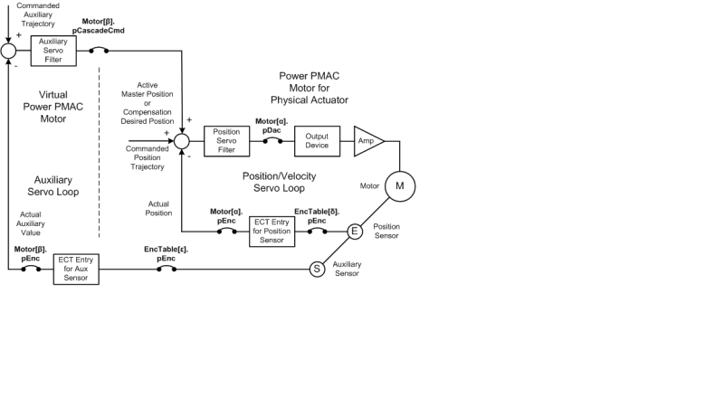
If I understand correctly what you are trying to do, we have successfully used an approach we call "cascaded servo loops" for many years now. (I am certainly not saying this is the only way.) We have used it with both electromechanical and electrohydraulic actuators, and systems ranging from giant press brakes on the large side to semiconductor wire bonding on the small side.

In this approach, the "inner loop" is a standard positioning loop, often a PID loop with standard reference trajectory inputs. It is used by itself when you are moving in free air. When the system comes in contact with the material it has to apply a force to, an outer force loop is engaged. There is a commanded force set point, a measured force feedback value, and a feedback filter (usually PI is enough).

The output of this feedback loop acts as a position offset command to the inner loop, adding to the trajectory-commanded value (which is usually not changing in this mode). If the measured force is less than commanded, the position command is offset further into the material; if it is greater than commanded, it is offset in the direction out of the material.

In our customers' experience over the last 25 years using this technique, it has not been difficult to get stability with these loops. They generally spend more time figuring out how to properly manage the transitions of engaging and disengaging the outer loop.

Here is a diagram we use in our manuals to explain the technique. The labels specific to our controller are not important to you. Focus on the loop topology.

Cascaded_Loops_Block_Diagram_Picture_eq1rll.png


Curt Wilson
Omron Delta Tau
 
Status
Not open for further replies.

Part and Inventory Search

Sponsor