Continue to Site

Eng-Tips is the largest engineering community on the Internet

Intelligent Work Forums for Engineering Professionals

  • Congratulations KootK on being selected by the Eng-Tips community for having the most helpful posts in the forums last week. Way to Go!

Coupling Seizure 3

Status
Not open for further replies.

bhaskar5150

Petroleum
Jul 6, 2016
15
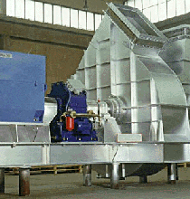
In our DCU plant, we have 2 nos of FD fans (identical) for supplying combustion air to the burners with the following data :
Flow : 10.896 m3/sec, Static pressure :4700 pa (479 MMWC), Rated power : 61.25 KW
Temp : 35C, RPM : 980, Motor rating : 75KW. Impeller type : Backward curved.

Each fan has a IGV at suction for flow control & discharge damper is full close or full open & has a full close command on individual motor trip. Heater has a trip on low combustion air pressure in individual ducts (4 passes) to the burners.(25MMWC trip pressure against a normal of 34MMWC in individual passes).

Fan-A has a inherent problem of coupling failure (more than 3 times, last one in Jun'16).It is a practice here to run both fans in parallel since its commissioning. Present flow is around 6.6 M3/sec & static pressure is 410 MMWC. This is done by throttling the IGVs of both the fans.(Control is single command for both IGVs) In all previous cases, the coupling bolts & shims break getting uncoupled with the motor but motor still running (doesn't trip), therefore doesn't closes the discharge damper & flow from Fan-B goes to Fan-A & reverse rotates the fan. (This is obvious & only a after effect of coupling seizure). Then, discharge damper of Fan-A is closed manually.

Another important fact is that normally after every start-up, one fan (Fan-B in last 3 cases) is started first as the flow requirement is less initially & after a certain time interval the 2nd fan (Fan-A in last 3 cases) is started and IGVs of both the fans are adjusted accordingly to get the desired flow & static pressure.

From above, it can be concluded the Fan-A starts against a back pressure (created by the static pressure of Fan-B). Is it because of this that the Fan-A never recovers under parallel operation, operates on the left of the peak pressure of the fan curve and goes under stall. Due to this flow reversal in fan-A, coupling shims & bolts breaks as they are weakest components in that line. Also, the stalling zone is not defined by the manufacturer in the individual fan curve.

Also, there is no vibration issues reported & so the factors such as misalignment, bend shaft, eccentricity, unbalance may be ruled out.

If above is the cause, how to know & confirm it.

We are finding it very difficult to access the parallel performance of the fans and have no idea how the combined curve would behave under the present operating conditions.

Any advice/suggestion to get a permanent solution to this problem.

Thanks in advance.
 
Replies continue below

Recommended for you

Does Fan-A have reverse shaft rotation prior to starting, indicating that discharge damper is not closed or is leaking?
Do the motors have electrical soft-start device?
Possible actions could include:
1) Verify discharge damper (actual) position prior to startup
2) Verify reverse rotation and shaft speed
3) Measure shaft torque transient (strain gage telemetry) and shaft speed during startup
4) Evaluate changing shaft coupling to a larger size or different type (elastomer or permanent magnet coupling)
5) Evaluate motor soft start device (electrical or permanent magnet shaft coupling)

Walt
 
"the coupling bolts & shims break"

too bad there aren't any pictures and drawings
.. yet

Sounds like this type of coupling.

The bolts break too?

The coupling manufacturer should be able to offer an opinion after seeing all the broken parts, and installation details.

There should be 2 separate shim packs

I would not count on vibration readings to discount misalignment or bent shafts or eccentric hubs.

I would watch the new coupling packs for puckering or bending when rotating the fan by hand,
Then repeat the inspection with a strobe light when the fan is first started.
Then repeat the inspection after each start of the second fan.

The use of the OEM curved or beveled faces washers is important for disc life. And they must be installed properly.
I'd discreetly check to see how they are being installed rather asking the millwright how they are doing it.

Here is a link with pictures of a few of the problems I mentioned.
 
Are the blowers truely identicle, or are they mirror images with opposite rotation? What is the manufacturer and model of the coupling? Are the motor drivers identicle?

Johnny Pellin
 
Thanks for the responses & valuable inputs.

Reply of Strong's questions :

a) There is no soft starter. Motor is a 6 pole, 3 phase, 415V, 75KW,124 FLA, 980 rpm; Make - Crompton Greaves; Frame-E315M and starting mode - DOL, Motor Starting torgue : 200% of Full load torque. Also, Fans full load torque = 584 NM at full IGV opening.(as per OEM data)
b) As already mentioned, Fan-01 starts against the back pressure of Fan-02 (already running), starts against reverse rotation as discharge damper is fully opened before starting.
c) Motor speed cannot be taken now as both fans are running & no tachometer installed. (Any other method available ?)
d) Shaft torque transient (strain Gage telemetry) : What results can be achieved through this & how it will contribute in the failure analysis. (I have no knowledge in this part, kindly help me with some literature, source books & also, name of good parties who does this)
e) Coupling selection seems OK as required " HP/100 rpm rating" is 10.20 (HP/100 Rating = HP x 100 x SF/RPM = 100 x 100 x 1 / 980; service factor taken as 1 for fans / blowers as per coupling manual) as against the rated "HP/100 rpm rating" of the coupling is 25. Coupling make : Unique transmission, Series-80, size-250; manual available in net). Max bore size for this coupling model is 90mm.
Motor shaft dia = 80mm & pump shaft dia = 65mm at location of hubs.

Reply to Tmmose's questions :

Yes, coupling is a spacer type (drop down type) with 2 disc packs without any overload bushes.The shim pack & bolts of the DE completely found damaged. (Attached few photos available). Installation was correct I suppose.

Reply to Pellin's questions :

Fan arrangement attached in the drawing (not mirror image). One in the left side fails. Fans & Motors are completely identical (Fan Make is TLT & other details already given above). One correction : Impeller type is hollow airfoil.

Another observation made (not sure, please comment) :
On 04.07.2016 (post failure), both the fans were running & following are the parameters recorded from DCS :
Static pressure before APH (03PIC802) – 173.73 MMWC
Total flow (03FI802) – 23643 kg/hr.
IGV opening on both fans : 40.46% (Auto Mode)
Current reading: 75A on each fan motor (in local ammeters)

From the current reading of 75A, motor output power (fan BKW) of each fan is coming as 42.39 KW (approx) considering a power factor of 0.85 & motor efficiency of 92.5% from data sheet. If we plot this in the individual power vs capacity curve for individual fans (as given by mnfg), we see that each fan should give flow of around 6.3 m3/sec ie 23616 m3/hr volumetric flow. Considering air density as 1.07 kg/m3, mass flow of each fan is coming as 24267 kg/hr. Since IGV opening is same at 40.46% on both the fans, ideally loads on both the fans should be equal & the total mass flow should be 24267 x 2 = 48535 kg/hr. But as per DCS figures, total flow is showing as 23643 kg/hr. This signifies that we are not getting a mass flow what is approximately expected or in other words, one fan is overpowering the other fan. (Why this is happening probably because Fan-01 starts against back pressure of Fan-02 which is already running!!!)

for further advice & inputs,please

Bhaskar
 
 http://files.engineering.com/getfile.aspx?folder=4b2133eb-5e19-42c9-83b6-f91ce9ecc3f9&file=Failed_Coupling,ph-2.jpg
Just for clarification, are you starting this fan while it is running in reverse with the discharge damper open?

"Fan-01 starts against the back pressure of Fan-02 (already running), starts against reverse rotation as discharge damper is fully opened before starting."

If this is the case, I would expect the possibility of coupling problems. It is never a good practice to start a machine that is already spinning in reverse. It would be better to start the fan with the damper closed and risk a short duration surge. Adding a ratcheting, anti-reverse mechanism would give you the best of both worlds and allow start-up with the damper open but the fan not reverse spinning. But, those mechanisms can be prone to problems. We only use those on our deep water wells and they have caused some failures.

Johnny Pellin
 
" service factor taken as 1 for fans / blowers ".
Capturing the starting surge peak amps will tell a different tale I believe, just as the reported coupling failures indicate.


Starting a heavy or large diameter fan across the lines is pretty strenuous.
Starting one that is spinning backwards requires FIRST stopping it, then a strenuous start.

At some point the motor shaft and the fan shaft may also object, and provide broken parts with fracture surfaces that match the text book examples of low cycle fatigue, starting from stress concentrating details like key seats, shoulders, threads, thread relief grooves.
 
Fan A breaks more couplings.

Fan 1 starts against reverse rotation.

Well there you go.
 
Measure fan speed with strobe-light tachometer. Shaft rotation direction can be visually or enhanced by touching shaft with piece of cardboard.
Measure torque to prove that coupling is undersized for startup transient, because of starting against reverse rotation.
Start Fan-A with discharge damper closed, and then open it when fan reaches full speed. There is generally no harm to fan for short operating time with damper closed. This should be cheaper that starting again reverse rotation.
A FluxDrive SmartCoupling ( can provide a mechanically soft-start even with reverse shaft rotation.

Walt
 
Interesting post, but it takes quite an investment of time to read and then mentally map. So sorry for the rhetorical questions.

Does the duct expand after the second fan inlet?
Why not at fan 2 inlet?
What is velocity pressure of desired fan A flow?
Can it overcome static at fan B?

My random thought is to install an inlet box on fan B and run fan A into fan B by shifting fan A outlet inline with inlet box on fan B, but I have no idea if the fan curve(s) get you to the operating point you want with fans in series.

Maybe install a fluid coupling.

fluid_coupled_fan_gkg8fy.gif
 
Thanks to everyone for such wonderful explanations & knowledge sharing.

We have already started thinking in the line of starting the motor by keeping damper closed & once speed reaches its full, we will be opening the damper full. (For this, we will have to reverse the interlock; that is OK). This will hopefully ensure starting & gaining its full speed without any back pressure from the other fan.

As far as measuring the fan speed is concerned, we have got tachometer but we have to install the reflective tape and for that we will have to stop one fan (that is not possible as of now). Piece of cardboard concept is also a nice tip. thanks strong.

Strong has mentioned this point "Measure torque to prove that coupling is undersized for startup transient, because of starting against reverse rotation."
This is not possible as of now as current trend is not available. But assuming that the measured torque is more than the required during start-up period (causing torque transients during start-up), will that carry forward in the steady state (ie once motor reaches its full rpm). ie. torque reversals happening in steady state. If that is true, then my above calculations appears correct ie one fan overpowering the other fan & causing flow reversals/therefore, torque transients.

On contrary to it, the current is showing steady at 75A (as of now in both fans running). Fan BKW comes at around 42.39 KW. Torque at this power comes as 413.03 Nm @980rpm.

My questions now are :
1) Even if flow reversals / torque reversals are taking place (just assuming), will it have no effect on current ie current fluctuations ?? But current is steady. (or considering big mass of the impeller-motor system, there will be no effect)
2) Since start-up current trend & therefore, start-up torque transients (during start-up) is not available but assuming flow reversals going on in Fan-01 at present (with flow calculations as shown), then how to ascertain torque reversals at this moment (2 fans running steady at 75A each). And from that how to ascertain that the coupling is undersized to handle torque reversals. (Note : rated torque of this coupling - 1780Nm & Peak Torque-3560Nm).

Also, checked the fluid drive smart coupling. This is a fantastic breakthrough !!thanks Strong!!. Will axial thrust have a effect in this type of coupling (although 1 fan bearing is fixed). Fluid coupling is also a good advice by dvd. Which one is having more buyback period??

I think I am getting nearer to the solution & hopefully will find the root cause.

Waiting for your kind comments & advice further,pl.
 
It seems a popular theory that starting while fan is rotating in reverse contributes to couplign failure. I don't understand that:

[ul]
[li]The initial electromagnetic accelerating torque during reverse rotation won't differ significantly from locked rotor torque (torque during start from standstill).[/li]
[li]The torque seen at the coupling during start in absense of torsional oscillations is[/li]
[li]_____Tcoupling = Telectromagnetic * Jfan/(Jfan + Jmotor) (neglecting role of Tfan)[/li]
[li]I don’t' see that the potential for torsional oscillations is significantly affected by reverse rotation.[/li]
[li]The torque we talk about during starting represents an average over one or more power cycles… there is actually a large superimposed ac component of torque varying at line-frequency which tends to result from the dc offset in stator currents after start. I don't see a significant change in this.[/li]
[li]The only change I see is the time it will take to accelerate. So the coupling may be exposed to the same large starting torques including oscillating torque for longer a period when started during reverse rotation, but it's not obvious to me that it would see a higher peak torque.[/li]
[li]I don't rule out that reverse rotation plays a role in coupling failure (as supported by the fact that the motor started this way breaks coupling) but the cause->effect explanation from reverse rotation to broken coupling would not be obvious to me. I'm not arguing, but interested if someone can explain better about the mechanism by which starting during reverse rotation would cause a broken coupling and whether this is a known/expected phenomenon.[/li]
[/ul]

Wouldn't a severe stall condition show up in vibration? I know rotating stall often shows up at 1/3x or harmonics ofr 1/3 rotationg speed. Also we might expect some broadband noise floor in vibration and possibly audible noise I'd think. You have ideal situation of two identical fans to compare against each other. If there is no significant difference between these two machines in terms of vibration patterns and noise, I would doubt the scenario that one is carrying full load and one is stalling.

Do you have a strobe light? If you are suspecting some torsional phenomenon you might get lucky and be able to see it when strobing the coupling and shaft at each end. Also if the coupling is Thomas/Rexnord shim pack then strobing the shim packs could potentially reveal some clues. While you're at it you can nail down the speed of the two machines for comparison.
My questions now are :
1) Even if flow reversals / torque reversals are taking place (just assuming), will it have no effect on current ie current fluctuations ?? But current is steady. (or considering big mass of the impeller-motor system, there will be no effect)
I would think that most scenarios that result in varying coupling torque result in varying motor current. Do you happen to have pump curves including bhp vs flow. I am curious if it is a relatively flat curve. It seems odd that a motor you suspect as stalling would draw same current as motor you suspect is carrying the full load (is that what you said is happening?)


=====================================
(2B)+(2B)' ?
 
EP, maybe the coupling has some backlash and it slams when it reverses?
 
Well that doesn't really work either since the fan blade would be driving the motor so any backlash would already be taken up.
 
The coupling does not immediately fails, last it failed on Jun'16 after running for 4 months from Feb,16. But since the fan is started against reverse rotation (discharge damper opens 1st on motor start initiative) and back pressure generated by the already running fan. But as per present flow calculations by using current method and plotting in KW vs Q curve, the total flow is coming almost double (since both fans sharing equal load ie 75A) as against DCS flow figures. Then where is the extra flow going. Hence, we are thinking that this fan is running under stall/ not contributing to the total flow.
Due to this flow reversals, torque transients might be taking place.

But will there be any current change/ fluctuations for these torque reversals? How to prove the coupling is underdesigned for this torque transient (if occurring).
Already raised these questions above against strong's earlier suggestion.

The blades are backward hollow airfoil type and fan curve is rising type. Stalling zone is not given by fan OEM. But flow shows at around 6m3/sec @75a in the curve for a single fan against a rated of 10.9 m3/sec. Stall zone will again increase for parallel fan operation.
 
Tmoose guessed at your coupling type as a Rexnord / Thomas shim pack style since you mentioned coupling shims. I'm going to ASSUME that's the case.

Because the flex element (the shim pack) is readily visible, this particular type of coupling sometimes gives clues as to the stresses it is seeing or has seen. So there is potentially a wealth of information available by carefully inspecting the coupling any of these times:
1 - during operation (*)
2 - during routine shutdown
3 - following failure

* inspecting during operation is obviously the trickiest. If you are lucky enough to have good line of site and room for a strobe then try that. But often you may be limited to looking up under the small gap at bottom of coupling guard and there's just not enough room for eyeballs and strobe under there. In that case you can try sliding a camera under there and try to get a few flash photos. Under the right conditions flash photography effectively freezes rotating components. It stands to reason it works best when the area is otherwise dark under the coupling guard and you have fast shutter speed and slow shaft rotation. I've frozen a 3600rpm coupling with my old style cameras... haven't tried it with a smartphone yet.

Here is a document devoted entiely to inspecting this type of coupling for clues about stresses during shutdown

For the case of torque overload, see figure 10. When you visualize the path of torque transmission through the coupling, you'll realize that it places a given shim pack in tension over some arcs and in compression over alternating arcs. The boundary between these arcs occurs at the bolts or bolt pairs. If you overload the coupling, the strain grows in each region and buckling begins in the region of compression. It is depicted here in shutdown condition... would only be visible if the condition was severe enough to cause the shim pack deformation to remain after stress removed. During operation with full torque (or torque overload) applied, it should be more readily visible (if you have a clear line of site and strobe).

If you have axial force transmitted by coupling, it will show in shape of disk packs. Signs of misalignment might be seen. And there's more in that document. Almost anything that will cause the disk pack to fail would likely be evident at some point during coupling inspection. And having a sister machine coupling also available for inspection is just begging you to make the comparison between them.

Side note - at our plant we've found ejected pieces of shim sitting under the coupling guard (that's a big of a warning sign!). It starts as the cracking depicted in figure 8, but when you get two cracks there is potential for a portion to get flung out, especially if it is an outer disk in the pack (that doesn't have friction on each side holding it in).

There is some logic to starting where any good detective would start.... which is at the scene of the crime! i.e. try to study the coupling itself carefully to draw clues from there, rather than starting with more remote observations and trying to tie them back to the coupling with various theories. That's just a thought...I realize that's not always practical and I can also understand why you want to pull the string to understand why the flows don't seem right.

=========
your question about current oscillationl... I still think current will oscillate in any scenario of oscillating coupling torque. I'll see if I can dig up some more relevant info or thoughts.


=====================================
(2B)+(2B)' ?
 
What a fantastic advice. I am just loving it. Thanks a lot !! EC

I have seen some patterns (after taking photos as suggested) similar to fig no.10 of your upload.

Seems that the coupling is going through torque overload as per the depicted analysis. Does this also mean that torque reversals are taking place, then source of torque reversals must be the flow reversals. But the current is steady; this is diluting our confirmation of torque reversals. (RPM measurement would be fantastic but that is not possible now). Or current would be steady assuming that the magnitude of torque reversals is less (since it runs for substantial amount of time & then fails) than the magnitude of coupling torque rating (1750Nm)& may be the coupling is not design for torque reversals although it may be within the rated coupling torgue.

But how to prove this point practically at this moment.

Pl advice.
 
Glad that it may have been helpful.

Did you have a chance to compare between machines?[sup][/sup] I'd be cautious about looking at only one...It's tougher to judge what is normal.

Still a little skeptical about torque reversals without current oscillation.

=====================================
(2B)+(2B)' ?
 
Yes, I did compare.

failed fan coupling has a bowed or bulged out shim pack but the other fan is OK (Shim pack clamped together without any bow/bulging). Will soon share the photos.
 
Status
Not open for further replies.

Part and Inventory Search

Sponsor