Eng-Tips is the largest engineering community on the Internet

Intelligent Work Forums for Engineering Professionals

Coupling Selection for Three Phase Induction Motor Started Direct on Line

Status
Not open for further replies.

fsxn155

Mechanical
Jun 29, 2020
29
0
0
QA
Dear All

We are facing problem of Coupling Failure on an Electric Motor Drive Centrifugal Compressor Train. The layout is as follows
Motor - Gear Box - LP Compressor - HP Compressor
The Motor is Squirrel Cage type 3 Phase Induction Motor (2 Pole, 2967 RPM, 50 Hz) started Direct On Line. As per Motor Curves, Motor can develop Peak Torque equal to 2.5 times Full Load Torque during Startup.
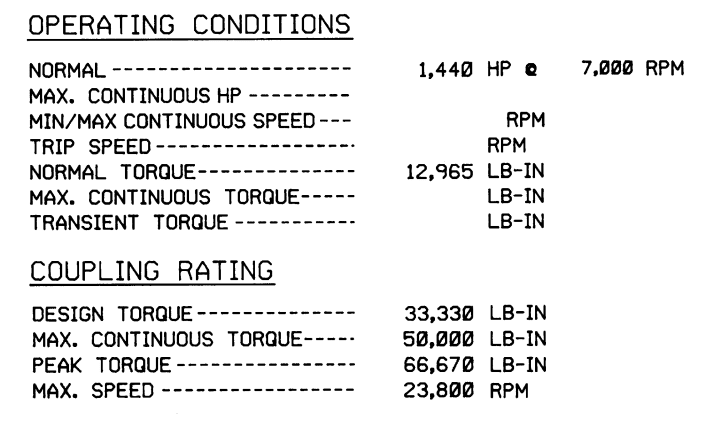
The Service Factor (Ratio of Max. Continuous Torque to Normal Torque) is 3.06 for Motor to Gear Box Coupling whereas this value is 2.16 for Gear Box to LP Compressor Coupling and 1.82 for LP to HP Coupling.
Ratio of Peak Torque Rating to Normal Torque for Gear Box to LP & LP to HP Coupling is 2.89 & 2.47 respectively.
Appreciate if anyone please help to understand the following

If Motor actually develops Peak Torque equal to 2.5 Times Full Load Torque during startup, Torque transmitted by Gear Box to LP and LP to HP Coupling will be increased by same factor of 2.5 ? and if so this implies G-Box to LP & LP to HP Couplings will fail after certain number of Start Stops as Couplings are designed to withstand Peak Torque for limited number of Cycles?
 
Replies continue below

Recommended for you

I feel like you answered your own question. The motor is capable of developing 2.5 times full load torque. But, the coupling would only see this much torque if the driven machine was offering that much resistance. That could probably only happen if the compressor seized up completely during start-up when the motor was at half of full speed. I prefer to review coupling ratings in units of torque rather than ratios. I tried to find the largest coupling I have on an induction motor with across the line starting. Our machine train has an induction motor coupled to a gearbox coupled to a compressor. This is the data for the high speed coupling. This has run for many decades with dozens of starts with no problems at all.

Capture_lho7pf.png


Johnny Pellin
 
Dear Johnny

Many Thanks for your feedback. Regarding your point "The motor is capable of developing 2.5 times full load torque. But, the coupling would only see this much torque if the driven machine was offering that much resistance", this is exactly what I was thinking initially.
But May I ask if it is possible that the Peak Torque developed by Motor is function of Electrical Parameters like Voltage Applied, Rotor Resistance Current Drawn etc. ?
During Start up, the Mechanical Load from Compressor Side is due to Inertia of the Train plus the Gas Load (Flow & Pressure differential). While calculating Starting Torque, another parameter to be considered is the time in which Compressor is ramped up to rated speed.
Increasing the Starting Torque with out increase in Mechanical Load will simply result in higher acceleration of the Compressor Train ?

During Startup, A Motor with capability of generating Torque equal to 2.5 Times the Full Load Torque can accelerate the Compressor to rated Speed
This is what I tend to believe when I look at the attached Curves
 
 https://files.engineering.com/getfile.aspx?folder=fc5a69c4-82e1-49c2-a77c-a930c16bd4e0&file=Motor_Curves.png
Dear Johnny
What I am thinking is while startup there is actually no Torque demand from Compressor Side. Its up to the Prime Mover Capability that how much angular acceleration it can impart to the Inertia of Compressor Train in ramping up to the rated speed
 
For me the issue will be inertia. A DOl starter in my experience is 0 - max speed in less than 5 seconds. With a gearbox, an LP and HP drive train the vast majority of torque is simply acceleration of those elements. Is there any vendor data on start-up torque over time ( first 5 seconds, unloaded)

Also agree with JJ as usual on using torque. For a gearbox you change the torque as well as the speed so the percents can get confused.

But yes, I read the OP and thought the answer was already there - you're putting too much torque through the coupling if only for 1-2 seconds, it's enough after a few starts to destroy the coupling. IMHO.

Remember - More details = better answers
Also: If you get a response it's polite to respond to it.
 
Could be a better option if you install a soft start arrangement.

It is a capital mistake to theorise before one has data. Insensibly one begins to twist facts to suit theories, instead of theories to suit facts. (Sherlock Holmes - A Scandal in Bohemia.)
 
fsxn: You also posed this question in one of the electric threads. If you look at the supplied motor torque/speed curves you attached to that message, you see that there is a different motor torque curve for 100 percent rated voltage (1.0 pu) and a lower one for reduced voltage (0.8 pu) WHEN THE MOTOR UNDERGOES A LINE START. This means you just close the breaker and let 'er rip. The motor guy is telling you to be careful that the high inrush current of the motor doesn't drop the line voltage too far, or the motor may not develop enough torque to accelerate the load within the desired time frame (set either by the system, or by the thermal capability of the rotor cage design).

So yes - the applied voltage affects the torque output. At lower voltages, the motor will draw less starting current as well. The proportions between these factors is fairly simple. The reason torque is a squared relationship is because torque is a function of power, which in turn is a function of (current)^2 * resistance.
(VOLT low)/(VOLT high) = (AMP low) / (AMP high) = [(TORQUE low)/(TORQUE high)]^2

Torque actually used during acceleration depends on where (on the torque/speed) curve the motor and load are at any given point in time. The difference between motor torque and load torque is the acceleration torque. More acceleration torque means either capability for higher load inertias, or faster to get to rated speed. From your earlier curves, the motor only develops about 0.6 pu torque at standstill with rated (1.0 pu) volts applied. If this is enough to begin turning the gearbox and shaft - which should be the case, given the load torque curve supplied - the system will accelerate. As soon as it begins to turn, the starting current begins to drop and consequently torque drops a little bit. Then the centrifugal load and added friction kicks in as we near rated speed, causing torque produced to climb again.

From JJ's post, it is typical to have the DESIGN rating of the coupling match the PEAK MOTOR TORQUE. Then you start putting in the safety factors, which results in COUPLING PEAK TORQUE capability. Usually, the COUPLING PEAK rating is related to the FAULT TORQUE of the motor.

Converting energy to motion for more than half a century
 
I would caution to be careful not to drastically overdesign your coupling. If you design for a condition that could only occur during a total wreck of the driven machine, then a coupling failure may the least of your problems. If you design for a set of conditions that will never occur, it can tend to make the coupling much larger, much heavier and much more expensive. Even if the cost is not a concern to you, the size and the weight should be. A very large, very heavy coupling changes your lateral and torsional rotor-dynamics. It imposes loads on the bearings on either side. It can create maintainability issues when your mechanics have to remove and install it. We have over 2000 couplings in service in our plant. We normally take the full design horsepower of the driver (motor or turbine) and design the coupling with a 1.5 or greater service factor over that condition. That determines the coupling design torque. The coupling manufacturer provides the max continuous torque value which may be another 50% above that and a peak torque capability which may be another 50% above that. Using that method, we have operated thousands of couplings for the 30+ years of my career and I can count the number of times I have seen a coupling fail from overload on my fingers. And, most of the coupling failures I have seen were on relatively small pumps (100 HP or less) that start and stop many times per day and run in very viscous services.

Work with the coupling manufacturer. They do this all the time. They do not want to sell you a coupling which will fail catastrophically in 5 years.

Johnny Pellin
 
Dear All
Many thanks for useful inputs from all of you. Your valuable cooperation is highly appreciated

Dear Gr8blu

Regarding your point "The difference between Motor Torque and Load Torque is the acceleration torque", I am still unable to understand what exactly controls this Motor Torque and Load Torque differential i.e. Acceleration Torque ? is it Motor Electrical Characteristic or Mechanical Load ? In other words from the attached Curves should I infer that for 100 % Rated Voltage Motor will develop a Peak Torque of 2.5 Times Full Load Torque irrespective of Load Torque. If Load Torque is less than what is on the Curve, Load will be accelerated to rated RPM in less time and if Load Torque is more, Peak Torque will remain same but Load will be accelerated to rated RPM in more time ?

Dear JJ
I fully agree with your concern but I still not understand when you say "If you design for a condition that could only occur during a total wreck of the driven machine".
Just to update you about the background, this Train originally had Shim Pack Coupling b/w Motor to Gear Box with Max. Cont. Torque 3.06 times full load Torque. This Coupling had Shear Pins designed to Shear at Torque slightly above Max. cont. Torque. However in order to address the Coupling Failures on this Train, this Coupling has recently been replaced with Torsionally Damped Diaphragm Coupling in attempt to eliminate possible Torsional Vibrations. Interestingly for the modified Coupling Max. Cont. Torque is 1.7 times normal Torque.

Also working on lines suggested by you, I have checked the Coupling Ratings on 3 other Three Phase Induction Motor driven Compressor Trains and the Motor to Gear Box Coupling in all 03 Trains have Max. Continuous Torque Rating exceeding the Peak Starting Torque given in Motor Curves. In fact in 02 of these 03 Trains for the other 02 Couplings (Gear Box to LP & LP to HP) the ratio of Max. Cont. Torque to Normal Torque is more than Ratio of Peak Torque to Full Load Torque given in Motor Curves.
Peak Torque Rating is above the Max. Cont. Torque Rating for all these Couplings but Couplings are designed to with stand Peak Torque for limited number of cycles probably meant to withstand fault Torque as suggested by Gr8blu

In nut shell my question is about having Coupling Maximum Continuous Rating equal to Peak Starting Torque as per Motor Curves not to have Max. Cont. Torque Rating equal to Motor Short Circuit Torque


Dear Gr8blu

In the attached Motor Curves, it can be seen that from 70% to 95% of rated Speed (0.7 - 0.95 on Speed Axis) the differential b/w Motor Starting Torque and Load Torque (lower most line in Curve) sharply increases i.e. there is sharp rise in Staring Torque which increases from around 0.9 X Full Load Torque to 2.5 X Full Load Torque whereas Load Torque increases from around 0.45 X Full Load Torque to 0.9 X Full Load Torque.

Does this sharp rise in Motor Starting Torque and Load Torque differential i.e. Acceleration Torque actually happens or its just a calculation reflecting Motor capability ? i.e. in actual differential b/w Motor Starting Torque & Load Torque i.e. Acceleration Torque remains same through out speed increase from 0 to 100 % ?

I have seen Motor Curves for 02 other similar Motors and these are similar to the attached Curves.
 
fsxn: The development of torque by the motor is a function of the strength of the magnetic fields in the rotating and non-rotating parts of the machine. Stronger magnets means force across the gap between moving and stationary parts, so more torque. The magnet field strength can be adjusted by current (if the magnet is an electro-magnet) or by distance (weaker force if distance is greater). Both of these methods are used by the motor designer. The amount of energy being used to overcome the desire of the rotor to stay still (i.e. slip) decreases with speed, so more is available for useful work - like acceleration.

The load torque is a function of the type of load (centrifugal or otherwise), inertias of moving components, friction and windage of moving components in the drive train, and the mechanical resistance of the process itself (e.g. air in a fan, water in a pump, etc.). Different loads react differently to speed changes.

To answer your question: the load actually does require the amount of effort portrayed in the curve, more or less. Outside factors could make it a bit harder or easier on the drive motor (for example, it gets harder to "push" colder air which has more density than warmer air), but the curve is a reasonable approximation if the one providing the curve understands the process correctly. The motor will develop torque up to the theoretical limits shown on the motor curve, too, within a reasonable estimation. The motor designer tries to keep enough margin between motor torque and load requirement to maintain acceleration: in some cases this is about 10% but could be as high as 20% or more, depending on user and application. Also note the two curves (motor and load) are not necessarily parallel through the speed range: this might mean motor has WAY more capability than necessary at some points, just to have barely enough at others.

And then there is always the "we'll use a -stock- design" approach, where the motor is good for a lot of similar things, including the proposed application. But it isn't necessarily optimized for the specific use.

Converting energy to motion for more than half a century
 
How much torque goes through the coupling depends on the inertia in the motor rotor, compared to the inertia in the gearbox/compressors. So torque through the coupling should be less than max torque of the motor. A portion of the torque has to accelerate the rotor.

Curious why you switched to a torsional damping coupling. Centrifugal compressors are not known for torsional vibrations (that I am aware of).

What was the problem with the original coupling system?
 
What kind of coupling is this?

I am curious if there is some sort of no-load condition that allows the motor to get up to synchronous speed, and then with a quickly developing load, there is a slowdown - sort of like (re-)starting a rotating load in reverse. Don't know much about compressors to know what type of start-up curve they go through. VFD always seems like a good investment in this era.
 
If you are using the same size / type coupling originally sized by the OEM, I would be surprised if it is mis-ized. Verifying this is fairly easy, use the method in the coupling catalog for the coupling installed. The method is usually based on driver size and a factor based on usage type.

If the coupling arrangement you currently have id different than the OEM arrangement, consider returning to the OEM arrangement.

I consider it more likely that you are fighting either a shaft alignment problem or a coupling lubrication problem.

My service experience with centrifugal compressors is that failures are very infrequent, compared with other equipment.
 
Status
Not open for further replies.
Back
Top