Continue to Site

Eng-Tips is the largest engineering community on the Internet

Intelligent Work Forums for Engineering Professionals

  • Congratulations KootK on being selected by the Eng-Tips community for having the most helpful posts in the forums last week. Way to Go!

Couplings and radial chock load 2

Status
Not open for further replies.

Verkstad

Mechanical
May 17, 2011
44
Hi!

I have a case as shown in the picture below. The shaft between the couplings have no support.
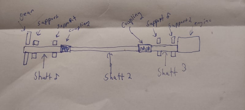
IMG_20230325_212656_cijysm.jpg


The problem is that i get shock loads but not when the engine is running. I have solved the case where i get a axiell shock load by pressing the axis toward each outer hence i get no axial movement of
the coupling (but it would be good to have a coupling who could handle some axial movement)

The case i am wondering about is when i get a radial shock load. I need a couplings with a rated torque of about 800Nm and i get a chock load in shaft 2 of 5kN hence 2,5kN on each coupling. Do you guys have any suggestion on what coupling i could use?
 
Replies continue below

Recommended for you

Yes i am in a conversation with a reseller it was he who suggested the idea to put the shaft together to deal with the axial shock. And if you ask a manufacturer you ask for a specfic coupling design which i have done. I think that you can use many venues :) to point you it the right direction. Since this is not a standard design it is complicated.

The reseller claimed that it was a bad design that shaft 2 has no support. But it is only moving in 16 rpm.
 
Hi Verkstad

Just what length is shaft 2 out of curiosity?

“Do not worry about your problems with mathematics, I assure you mine are far greater.” Albert Einstein
 
2 meter hence the angle become small since the tolerance of the supports are good. And you can put a concentricity tolerance on the shaft between the edges where the coupling are being clamped.
 
Hi Verkstad

Thanks for the reply, I wonder if the coupling manufacturer was concerned about the static deflection of shaft 2 without supports, maybe he thought the deflection of the shaft might exceed the angular alignment of the couplings if the shaft was unsupported.

“Do not worry about your problems with mathematics, I assure you mine are far greater.” Albert Einstein
 
I'm not very familiar with setups like that. I'll throw in some thoughts fwiw

In our power plant the only spacer couplings we have are only as long as they need to be to facilitate maintenance. But I understand other places do things differnrtly if for some reason it's not possible to put the driver close to the driven.

Just thinking out loud the only potential problems I can think of with a long spacer are:
1 - extra weight to load the bearings
2 - potential to sag in the midspan, which might resemble misalignment if the bearing pairs on each side are aligned across with lasers. There is some kind of special alignment procedure on long flexible turbine trains to account for sag (catenary curve).
3 - potential for resonance of a long unsupported shaft section at a low frequency which might correspond to an excitation (admittedly you can get in trouble lots of ways with resonance, not just long shafts)

It strikes me some or all of the above can be helped by a hollow shaft. For a given torque capability (polar moment of inertia) it has less weight which helps 1. For a given bending moment of inertia it has less weight (helps 2 and maybe 3).
 
I had meating with the reseller snd there technical expert and they now believe in the design with a jaw coupling. But we will talk with the coupling company about the radial shock.But the technical expert wasn't concerned.
 
Make certain that your shaft arrangement allows for the installation and removal of the jaw coupling without additional disassembly - i.e., can the jaw coupling half slip forward enough to allow the element and other half to be removed without removing bearings or other equipment. Same goes for any other coupling choice - investigate to assure that the coupling can be installed and removed without unnecessary disassembly.
 
Generally in automotive we avoid fancy couplings for cost and durability's sake. If the max displacement between 1&3 is fairly small then I would simply use a pair of splines on either end and allow 2 to float axially. If the required displacement is large then I would use splines and universal joints as necessary.
 
Status
Not open for further replies.

Part and Inventory Search

Sponsor