Continue to Site

Eng-Tips is the largest engineering community on the Internet

Intelligent Work Forums for Engineering Professionals

  • Congratulations MintJulep on being selected by the Eng-Tips community for having the most helpful posts in the forums last week. Way to Go!

Crack in the weld transverse to the direction of weld run 3

Status
Not open for further replies.

rtiwari123

Mechanical
Mar 22, 2016
8
Hi Al,

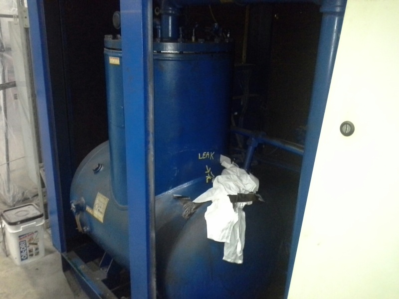
Can anyone take a look at the two pictures below and advise the cause for the fracture shown here.

Fracture_in_Vessel_-_1_sz2wad.jpg

Fracture_in_Vessel_-_2_ckie5u.jpg


It is an oil separator tank made from SA 455 material. To my knowledge there are no temperature extremes and vibrations in service. Material is 0.25" thick; it is code vessel. Thanks in advance.
 
Replies continue below

Recommended for you

If it is a NB/ASME code pressure vessel, there should be a tack welded nameplate with a National Board number. Providing the NB number to the National Board, you can get a copy of the manufacturer's data sheet. I got a feeling that you have a Chinese clone which was cheaply purchased. If there are no nameplate get rid of it and get a NB code constructed unit.
 
Yeah, I now see it too Compositepro as it is tack welded on the tower section.
 
The nozzle diameter is almost the diameter of the vessel. Unfortunately there is no information about the pressure, temperature, materials and wall thicknesses. It seems to me that there is a lack of nozzle reinforcement, therefore the weld is highly stressed. The direction of crack and location are the clear proves of it.
 
Saplanti, that was my point, maybe it's just bad design rather than bad construction, especially if it's happened more than once in the same place.

Remember - More details = better answers
Also: If you get a response it's polite to respond to it.
 
How is the material of construction known to be is SA 455?

If that information is known, the operating temperature and pressure should be known or the information should be located on the attached nameplate. My point being, there should be a bit more information available or obtainable from the source that knew the material of construction.

There have been several hypothesis tossed out, but without sufficient information they are no more than speculations as to the cause. There is a couple that I find interesting and worth looking into:
1) Proper design: It seems likely that the opening should have been reinforced considering both major components are nearly the same diameter.
2) Stress: The hoop stress usually exceeds the axial stress and the crack is oriented transverse to the hoop stress.
3) Welding: The carbon content is typically below 0.3% and the wall thickness is ¼ inch, so it doubtful preheat is necessary and less likely to have been provided. The likelihood of hydrogen cracking seems low with the thickness and carbon equivalency involved.
4) Weld defects: The presence of a weld discontinuity is relatively high regardless of whether a complete joint penetration groove weld was employed or if for some reason the fabricator used fillet welds to join the two major components. If this is an ASME designed and fabricated vessel one would expect a CJP groove weld was used. That isn’t necessarily the case if it was constructed to a different design standard. The probability of incomplete joint penetration is high if the complete joint penetration groove was welded from one side. If the joint was back gouged, it is not uncommon for the welder to skimp on the depth and width of the back gouge especially considering it has been stated the thickness is only ¼ inch. Welders often leave remnants of the unfused root with the assumption they will “melt it out” with the next bead. Incomplete joint penetration is a common problem. If the width of the back gouge is insufficient, incomplete fusion can often result as the weld flows into the BG cavity but doesn’t fuse to the groove face of the excavation.
If the joint was designed as a fillet weld, the root acts as a crack initiation point. If the initiation point of a weld bead is not properly fused, it acts as a stress riser and a possible location for crack initiation. While the weld profile in the photograph is uniform, unless this is a standard product that employs mechanized or automatic welding equipment, the welds are most likely deposited using a semi-automatic welding process. The welder cannot weld the entire perimeter of the joint without starting and stopping several times. Each time the weld is initiated, a “cold start” is a potential crack initiation point. Good practice would include a grinding operation to remove the “cold start”, but good practice is not always the common practice.


Best regards - Al
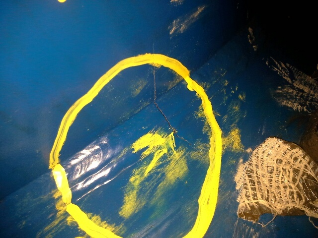
 
Probably the designer took into consideration the number of weld passes as reinforcement. I am estimating six weld passes including the root weld.
 
Gtaw:
Nicely done. Your comments on this thread have been right on the money. That’s about all that could possible be said, without guessing, and with so little of the important design info being kept secret. It never ceases to amaze me that people who claim to be engineering or tech professionals don’t seem to have any idea what info. is needed to be provided, if they want to start a meaningful discussion about their problem.
 
I see that the crack is across the weld. It's stress on the tank guys. The huge opening for the dome must be reinforced regardless of calculations so this design qualify for more analisys period. It may even need pwht. I'm surprised deformation did not show during hydrostatic test. T
As the poster says it's common n on this product, then also qualifies to be reported to the National al Board. That is if the Code is the ASME. Or the jurisdiction if in the US or Canada. GenBlr.
 
If it were reported to the National Board and investigated by it, there would be an article in one of their bulletins.
 
Status
Not open for further replies.

Part and Inventory Search

Sponsor