Eng-Tips is the largest engineering community on the Internet

Intelligent Work Forums for Engineering Professionals

Cracking in multispan rc beams

Status
Not open for further replies.

Quasar87

Civil/Environmental
Mar 4, 2024
10
0
0
SE
Hello,
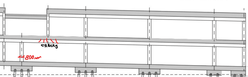
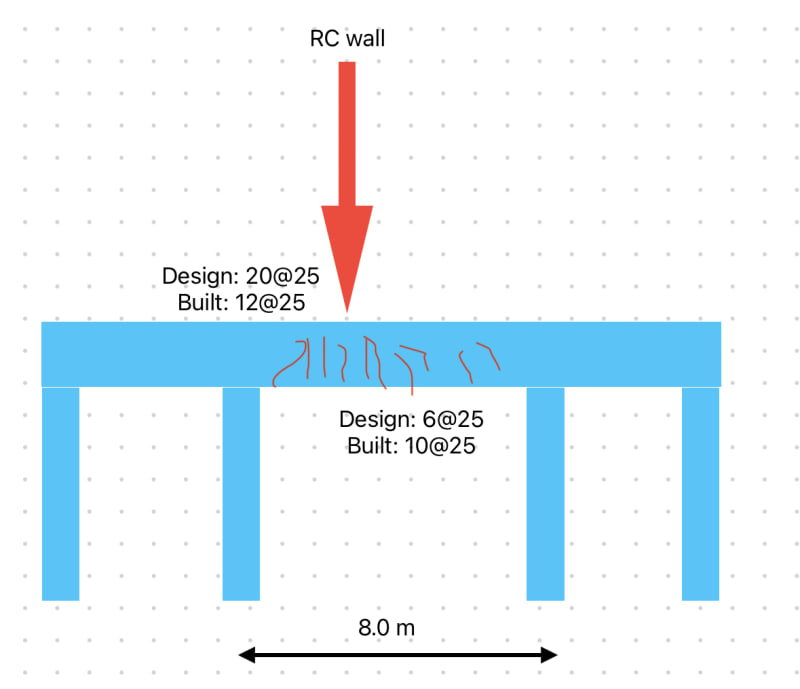
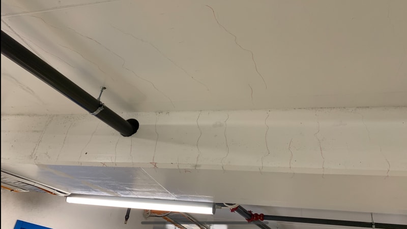
I’m in the process of assessing a continuous cast-in-place RC beam in a structure. The beam is designed originally as a T-beam and carries typical loads in a parking garage. In one span (8-m-long shown in the sketch) there is a rc wall that transfers all the load from the upper stories and is quite significant. The issue: severly cracked at the bottom right under the wall but with the crack widths just under the limit under permanenent loads only (no cars yet).
I’ve been asked to take a look as to why has cracked and this are the facts:
- beam originally designed to have 6 bars dia. 25 mm at the bottom and 20 bars at the top at the support.
- due to an error on the drawings the beam gets reinforced with 10 bars at the bottom and only 12 at support.

Now although the beam is reinforced extra at the bottom than original design and under-reinforced at the support it cracks significantly in the field.

I run my own analysis and in order to limit the cracks to the code I would need 9 bars in the field and and a lot more (25 bars) at the support.

My question:
Assuming no overloading has taken place why does it crack so much although there are more bars than my analysis shows I would need at the bottom
IMG_8358_skkupy.jpg
. Could there be any connection with the fact that a lot of bars are missing at the support (although no cracks has been noticed around support).
 
Replies continue below

Recommended for you

Can you post a picture of the as-built condition and pictures of surrounding beam elements for comparison? Top / bot / side if you have them.
 
IMG_8360_nykfam.jpg
URL]


Here is one photo showing the cracking on the beam. Directly above the beam (approx. where the pipe goes) is the rc wall (red arrow in my original post)
 
It appears that most of the cracks do not cross the bottom of the beam, is that correct? They certainly look like flexural cracks and given the load above plus poor placement of the sprinkler main that seems to fit. However, the lack of cracks at the bottom of the beam is peculiar. How much skin reinforcement was provided?

I'm not entirely convinced given the nature of the loading that T-beam analysis is appropriate. If you perform a straight beam analysis how much reinforcing is required? (might not change it depending on where compression block lands just something to check).

Also, you say that no cracks have been noted at the support. I assume you're talking about the top of the slab (not the bottom) at these locations? So the slab is visible and not covered beneath waterproofing or something?
 
The cracks are visible at the bottom as well; maybe not in the photo as it has been covered by paint. Aling the height of the beam (800mm) there are two extro longitudinal bars diam 16 mm and stirrups and stirrups di.16/100 mm.
I have only performed a T-section analysis. Why do you think woould be more suited a rectangular only , i.e skipping the flange in compression.

Yes, the slab is visible, it is the driving surface on the next floor. I looked around the supports and there are no cracks. The concrete is not covered with membrane/asphalt that could hide the cracks.
 
The original design with 20 top and 6 bottom is obviously wrong.

And I doubt 25 top and 9 bottom is correct either.

How stiff are the columns. It looks like there could be restraint to shortening involved also.

As we have no other information it is hard to comment further.
 
rapt - would restraint to shortening cracks not extend around to the bottom of the beam too? I think that's what is most puzzling for me as well, why do the cracks not propagate on the bottom surface..
 
The cracks in the slab perpendicular to the beam are definitely restraint shrinkage cracks. Agree with rapt that the beam cracks could be at least partly restraint cracking as well. If the columns are stiff enough, they could form stiff frames at each end which would resist shortening of the beam.
 
Luceid

Quasar87 said the cracks are on the bottom as well.

Hokie, And the beams are cracked around the point of contraflexure!

And the beam cracking appears to be fairly constant width up to the underside of the slab.
 
So to summarize, it looks like direct tension cracking due to restraint, not flexural cracking. I would expect to see some flexural cracking in the outside face of the columns.
 
@ QUASAR,

You did not supply a lot of info . here to see the reason. Apparently , the cracks developed under the wall ( hogging section ) , not at supports , not along the length of the beam right?.

The reinf . original design= 6 T 25 mm Bottom + 20 T 25 mm Top
The reinf . as built = 10 T 25 mm Bottom + 12 T 25 mm Top
The reinf . as per your calc. = 9 T 25 mm Bottom + 25 T 25 mm Top .

Non of these reinf. justify the total moment ( ql^2/8 for UDL , PL/4 for concentrated load ) and max . moment which can develop at support.
In this case, ( with a very limited info. provided , ) this would be a guessing game.
I guess , the 8 m span is aisle width and the two side spans (6 m) parking widths. The typical reinf. at bottom 12 m length provided from beginning right end and all the bottom bars spliced at one place. So the cracks are bond cracks.


He is like a man building a house, who dug deep and laid the foundation on the rock. And when the flood arose, the stream beat vehemently against that house, and could not shake it, for it was founded on the rock..

Luke 6:48

 
Hello and thank you for your help. Now to provide more details:

1) The structure is a 2-storey building meaning I have a plate on ground then a Floor #1 (where the cracking occurred) and a roof. On Floor #1 is to be a parking garage. On the roof future loading is to be traffic loads 20kN/m2.
2) The beam has variable span length but not really large difference. See the new sketch which is on scale. The sketch shows a longitudinal section through the building.
The wall runs transversally throughout the whole building and all beams on which it rests has cracked​
section_kcwjbj.png

3) on the roof there is ballast to level up the rood - total load varies but is safe to say we have about 60 kn/m2 near the wall.
4) the wall supports the roof floor and transfers the load to the beam that cracked.
5) The beam presents flexural cracks. I agree there are some shrinkage cracks as well but those cracks are in my opinion definetely flexural cracks. They are widest at the bottom of the beam about 0.4 mm and gets thinner as they go up to the intrados of the slab.
6) Columns are about 800 mm in diameter. The beam is 800x850 mm with ba slab thickness 400 mm.
9) Someone said it doesnt make sense the amount of reinforcement neither in my calculation. Just want to point out that reinforcement is governed by serviceiability conditions to keep the crack widths low. Thus, the bottom cracks can be up to 0.4 mm while top of the slab and above the support should not exceed 0.2 mm; this is because of different exposure classes.
 
@ QUASAR,

Can you dedect the bottom reinf. with UT , RT ( the sizes, no. of rebars , lap locations ..) and the floor plans ?
The ht of RC wall is another question which the behavior would be deep beam . How the reinf. of the wall planted? What long. reinf. provided ?


He is like a man building a house, who dug deep and laid the foundation on the rock. And when the flood arose, the stream beat vehemently against that house, and could not shake it, for it was founded on the rock..

Luke 6:48


@HTURKAK
The wall has no signs of cracking. It is reinforced with 2 mesh layers dia.12/100 plus extra long. bars 3+3 dia.25 at the base.

I have detected the size and no. of rebars (not sure what is UT, RT). No idea where the lapping is done and it isn't documented either.

 
Seems pretty obvious to this aircraft stress engineer that the cracking occurred due to a high point load in the center of the beam span combined with insufficient reinforcement.
The real question/task is how to fix it. Demo it and rebuild? Reinforce with carbon fiber wraps?
 
@SWComposites CFRP strengthening most likely. But before that someone must be assume the mistake. While it is obvious a flexural issue the calculations doesnt show that you would need more reinforcement than what has been provided.

The question is if the support reinforcement, or better said lack of it since it was provided less then what the calculations shows, have initiated a redistribution of support moments to the field moments.
 
Redistribution of moments in that way is rather unlikely if you haven't exceeded the modulus of rupture over the support, and since there is no identifiable cracking on the top slab surface it would be a tough go to justify that as a primary cause for the cracking.

I agree with others in the possibility of shrinkage cracking. In situations like this you need to walk the structure to see what its normal is so to speak. In adjacent bays with similar spans / construction but without the RC wall above do we experience the same pattern of cracking (even if much smaller widths) or any cracking visible to the naked eye at all?

The next thing I would look at is the assumption of not being overloaded. Even if it's not overloaded at present perhaps it was overloaded at an earlier stage in the construction cycle. Things we'd like to know

A) What is the in-situ concrete strength and how does it compare to design
B) Were the cylinder breaks normal in terms of progression or were they delayed (e.g. 28 days was achieved at 56 days)
C) Any possibility for early-age construction loading impacting this location (e.g. stockpile of skids)
D) When were the forms stripped
E) When was the sprinkler main cored
 
@Enable Thanks for the good input.
Yes, I noticed fewer cracks and narrower in most of the spans. Those cracks were mostly at the bottom of the beam and perhaps 5-10 cm up. Could you please elaborate on rhis or what exactly is the connection?

I’m going to check on those points you raised although won’t be easy. At this point no ine wants to share much other than what is oficially been documented.

 
They may not want to share, but that information is necessary to have the whole picture in place. They can either provide it now so that everyone can determine the cause without lawyers, or it can get ugly and the lawyers will make sure all of that information comes to light, regardless of who it points the finger at.
 
Status
Not open for further replies.
Back
Top