Hello,
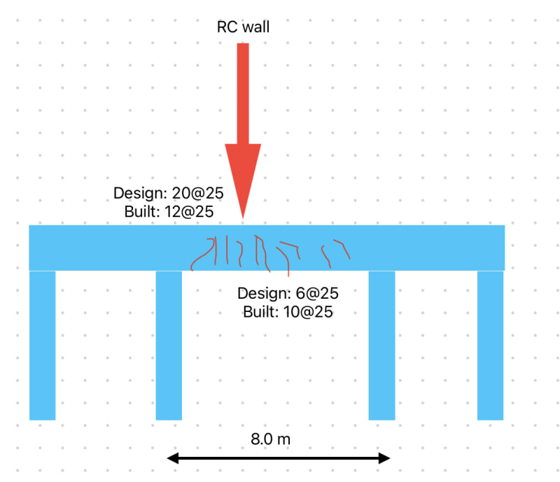
I’m in the process of assessing a continuous cast-in-place RC beam in a structure. The beam is designed originally as a T-beam and carries typical loads in a parking garage. In one span (8-m-long shown in the sketch) there is a rc wall that transfers all the load from the upper stories and is quite significant. The issue: severly cracked at the bottom right under the wall but with the crack widths just under the limit under permanenent loads only (no cars yet).
I’ve been asked to take a look as to why has cracked and this are the facts:
- beam originally designed to have 6 bars dia. 25 mm at the bottom and 20 bars at the top at the support.
- due to an error on the drawings the beam gets reinforced with 10 bars at the bottom and only 12 at support.
Now although the beam is reinforced extra at the bottom than original design and under-reinforced at the support it cracks significantly in the field.
I run my own analysis and in order to limit the cracks to the code I would need 9 bars in the field and and a lot more (25 bars) at the support.
My question:
Assuming no overloading has taken place why does it crack so much although there are more bars than my analysis shows I would need at the bottom
 . Could there be any connection with the fact that a lot of bars are missing at the support (although no cracks has been noticed around support).
I’m in the process of assessing a continuous cast-in-place RC beam in a structure. The beam is designed originally as a T-beam and carries typical loads in a parking garage. In one span (8-m-long shown in the sketch) there is a rc wall that transfers all the load from the upper stories and is quite significant. The issue: severly cracked at the bottom right under the wall but with the crack widths just under the limit under permanenent loads only (no cars yet).
I’ve been asked to take a look as to why has cracked and this are the facts:
- beam originally designed to have 6 bars dia. 25 mm at the bottom and 20 bars at the top at the support.
- due to an error on the drawings the beam gets reinforced with 10 bars at the bottom and only 12 at support.
Now although the beam is reinforced extra at the bottom than original design and under-reinforced at the support it cracks significantly in the field.
I run my own analysis and in order to limit the cracks to the code I would need 9 bars in the field and and a lot more (25 bars) at the support.
My question:
Assuming no overloading has taken place why does it crack so much although there are more bars than my analysis shows I would need at the bottom

