Continue to Site

Eng-Tips is the largest engineering community on the Internet

Intelligent Work Forums for Engineering Professionals

  • Congratulations IDS on being selected by the Eng-Tips community for having the most helpful posts in the forums last week. Way to Go!

Crane Column Reinforcing

Status
Not open for further replies.

SteelPE

Structural
Mar 9, 2006
2,759
I am in the process of putting an addition on an existing industrial building with some interior cranes (circa late 60’s). The building is 3 bays wide and currently has all three bays occupied with cranes. We are going to remove the end wall of the building to put on our addition. We are going to be placing new columns 1’-6” away from the existing building columns. Current code = IBC 2015.

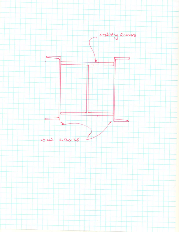
I am a bit uncomfortable with the existing end wall columns…. And actually, most of the columns inside of the existing building. No matter how I run my analysis, I just can’t get the existing columns end wall columns to work (I am guessing this is because of the computer analysis I am doing today vs the way it was designed 50+ years ago). So, after much thinking I have decided that I am going to apply some channels across the tips of the flanges (see attached) and make a box section out of the existing column. Based upon my rough analysis, I can get the columns to work with this reinforcing (full height).
img170_xliq59.jpg


The question revolves around welding of the channels to the columns. Since this loading is going to be cyclical (due to the cranes) should this weld be continuous or could it be intermittent (stitch welded on)?
 
Replies continue below

Recommended for you

Can you spin the channels so they are on the flanges, and then bolt them? Otherwise I would want full length welds with no stitches. That being said, the only time I inspected a crane with stitch welds (between a capped channel and the main girder forming the runway no less), the welds looked fine after 50+ years.
 
Can you use plate instead of columns? I'm surprised the old doesn't work... my experience is that the older methods of design were more conservative than more recent design.

So strange to see the singularity approaching while the entire planet is rapidly turning into a hellscape. -John Coates

-Dik
 
I agree with canwest's assessment that the welds ought to be continuous.
 
dik said:
my experience is that the older methods of design were more conservative than more recent design.

I understand what you are talking about. Maybe my methods are just really conservative, or possibly they installed a some larger cranes in the building and never really bothered to check the existing columns.
All my project requires is to remove the end wall and extend the building, so the remaining portion of the building really isn't my concern at this time. I have relayed my concerns to my client and told them about the necessary reinforcing. They were open to the idea at this point.

canwesteng said:
Can you spin the channels so they are on the flanges, and then bolt them?

If I do this, they can't be continuous as the reinforcing will interfere with the existing crane brackets. This is why I wanted to add the channels across the tips of the column flanges..... plus, by the time we are done, we will have a nice box section which will greatly reduce torsion created by the traction force of the cranes.
 
By placing the channels as shown, are you eliminating access/visibility of the anchor rods (if anchor rods are inside flanges)?

If so, you may want to consider another reinforcing configuration such as only adding reinforcing to the flanges.
This being a crane structure, one needs to keep an eye on all connections for loosening, fatigue, etc.

Agree with continuous welds instead of intermittent welds (more subject to fatigue due to starting and stopping of the weld line)
 
I am not sure if I am missing some terminology, but the anchor rods are buried below the existing slab. So they are not visible at all even in the current configuration.

I really don't want to be messing with the existing brackets as I think that will just cause more issues than it's going to solve.... and stopping and starting the reinforcing at the bracket defeats the purpose.
 
It wasn't a criticism of your methods... old working stress design for steel and concrete was generally more conservative... concrete flexure and compression in particular. The plate reinforcing doesn't necessarily have to go to the baseplate. Often a foot shy is OK... just a matter of checking the column as a stub column... buckling doesn't enter into it. I was questioned on that by a plant engineer a few decades back... also reinforcing across the toes as opposed to the flange. [pipe]

So strange to see the singularity approaching while the entire planet is rapidly turning into a hellscape. -John Coates

-Dik
 
Do you really need the channels to continue past the crane bracket? I would think that the portion of the column above the crane is ok, or at least you haven't the loading condition in any meaningful way. Even if old methods were conservative, at least at the end wall you've significantly increased load on the columns, as the crane wheels can now be more centred on the column than before (where an end stop would have stopped them somewhat shy).
 
canwesteng said:
Do you really need the channels to continue past the crane bracket?

You have a very good point there....... the reinforcing doesn't need to be full height. However, I would probably run it past the top rail of the crane 18 inches or so to make sure we have captured the loads in the reinforcing.
 
To piggyback on top of what canwesteng said, crane column cap channels are welded to crane girders with intermittent stich welds. Those welds can sometimes see tension if the lateral load is enough to overcome the compression in the top flange but they definitely see a lot of shear.

The welds in the suggested reinforcement would only ever see compression which isn't subject to fatigue, at least due to these cranes. Exterior column locations might see tension based on environmental loads but those aren't a concern for fatigue either. All that is to say, why wouldn't the welds be able to be intermittent?

Another factor is the material warping due to the heat of continuous welds. In my company's fabrication plant, a lot of work is performed to bend materials back into place during fabrication due to warping caused by welding. This is in an environment that's set up to handle those issues. They always want to do intermittent welds. I think if a welder were to get these welds full length in the field, they'd have to do this section here, then the opposite side a little and do a bunch of parts and pieces in different locations before finally finishing a complete full weld. That's going to get a lot of pushback as soon as the work is bid. You'll likely be put under pressure to change your design or justify requiring full length welds. If that happens, what's the justification? (That question is not to imply that there is no justification. It's to solicit comments that explain why a continuous weld is justified/required.)

On a separate note, do the columns really require reinforcing at all? If they've been functioning as intended since the 60s with no sign of problems, that's a pretty good indication they're up to the task. Another way to put it is when the results of your experiment don't match your prediction, and you know the experiment was done correctly, it's your prediction that needs to be addressed. Maybe you've made a simplifying assumption about the steel grades that were available back then that isn't accurate. That type of thing.

Finally, I've seen crane columns reinforced for much larger loads by just welding a new I shape on the inside flange that butts up against the bracket and carries the load to the ground. I don't know what load cases are controlling but something like this would cut the amount of weld in half.

I_Shape_Reinforcement_cj58ji.png
 
Sandwich,

To address a few of your points:

SandwichEngine said:
crane column cap channels are welded to crane girders with intermittent stich welds

I had a post about this some 8 years or so. I wanted to stitch weld a channel cap onto a crane girder. I has a post about it here and I was told that stitch welds on crane girder caps were a big NO! On that project I ended up with a mistake in my channel selection that I never picked up (a unit conversion that didn't happen properly) and I has the crane girder sizing taken away from my contract (not a big deal as the crane mfr took it over). When I was given the girder information from the manufacturer the channel caps were fully welded to the top of the beams further reinforcing this idea.

SandwichEngine said:
The welds in the suggested reinforcement would only ever see compression which isn't subject to fatigue

These welds will see the side thrust loads and traction/torsion loads generated by the crane. So while there isn't any full stress reversal, there is still some repeated loading and unloading of the fillets multiple times per day.

SandwichEngine said:
On a separate note, do the columns really require reinforcing at all? If they've been functioning as intended since the 60s with no sign of problems, that's a pretty good indication they're up to the task.

This point hits home. I get it, but in the end, you are not fully understanding the situation. We are removing the end wall siding material with consists of 6" precast plank capped with a WF beam and metal siding above. While I only see "clamps" attaching the plank to the columns, and I don't see any attachment of the WF beam cap to the plank, I can't be sure there isn't some attachment of the plank to this perimeter column. I went back last week to measure other interior columns to see if there were the same size, and the other interior columns were larger in size. There are a few other factors as well, but in in end, I decided that reinforcing was the best option (believe me, I don't want to do it).
 
SandwichEngine said:
On a separate note, do the columns really require reinforcing at all? If they've been functioning as intended since the 60s with no sign of problems, that's a pretty good indication they're up to the task. Another way to put it is when the results of your experiment don't match your prediction, and you know the experiment was done correctly, it's your prediction that needs to be addressed. Maybe you've made a simplifying assumption about the steel grades that were available back then that isn't accurate. That type of thing.

You may be comparing apples to apples here, but I would say that you're comparing a wild crab apple to a Fuji. The results of a single experiment or observation have very little weight when compared to long standing analysis and design procedures, code requirements, and the standard of care. While I agree that long term use should allow us some relaxation of the factor of safety as it relates to material capacity, that's only one small piece of that puzzle. Is it the original crane? Have any of the columns been damaged, corroded? Could it be that the column really is beyond current code limits, the steel is the strength SteelPE thinks it is, and the loading is accurate...we're just cutting into the factor of safety and it's simply operating with reduced reliability? Or perhaps they've never fully loaded the crane.

I'm all for pursuing the best, most efficient, and most cost effective design solutions and 'trimming the fat' where it makes sense to do so. But I often get the feeling that, in our attempts to do so (to satisfy a client, to avoid a conflict with a contractor, etc.) we lose site of just how complex these criteria actually are that we want to wish away.
 
Status
Not open for further replies.

Part and Inventory Search

Sponsor