Eng-Tips is the largest engineering community on the Internet

Intelligent Work Forums for Engineering Professionals

Crane load surcharge on retaining wall 2

Status
Not open for further replies.

Ayush Atriwal

Structural
Mar 8, 2020
1
0
0
US
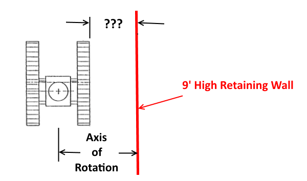
I am designing a 9 ft deep retaining wall which will support the load of a crane 6 ft from its face. From the technical sheet (attached), the weight of the crane is about 211 kips and the maximum base reaction on its belt will be about 52.6 psi (7500 psf). Applying Bousseniq's equation for lateral pressure, this gives me pressures over 1500 psf! I am afraid I am doing something wrong because there is no way a 12" thick wall can support those lateral pressures unless restrained somehow at the top. How do you guys design retaining walls for such cases?
 
 https://files.engineering.com/getfile.aspx?folder=c5303590-25a5-4219-9982-f785846f487b&file=ground_bearing_presures.pdf
Replies continue below

Recommended for you

Well, just off the top of my head, per AASHTO, for a HL-93 (or HS-20) truck, the surcharge on a wall that height would be equivalent to 3' of soil, or 360 psf, vertical load for a 32 kip axle. Multiplied by an active soil coefficient of, say 0.4, the unfactored lateral pressure would be 144 psf. Using the ratio of your load to the HL-93 axle load, the unfactored pressure would be around 950 psf, so 1500 psf doesn't seem unreasonable at all to me.

As far as how to design it, I suggest a thicker wall with more reinforcement, or a different type of wall, unless you're limited to a 12" thick wall for some reason.

Rod Smith, P.E., The artist formerly known as HotRod10
 
Another option is to use a different type of wall. MSE walls are fairly common for this type of application. The front to back width of the MSE is typically greater than a cantilever type, but it's a good solution if you're not limited on the excavation width behind the wall.

Rod Smith, P.E., The artist formerly known as HotRod10
 
Is this crane be staged permanently, or only a set duration? For either situation, it is better to spread out the load by using stiff ground support, rather that let it free roaring over the site.
 
I check sheeting walls for crane surcharges probably a couple times a month. With a 7500 psf strip surcharge from the nearest crane crawler track, you will probably need crane mats under both crawler tracks. You did not say what type of wall it is, but even with properly designed crane mats, a cantilevered wall most likely will not support the crane. The 6 foot offset helps you but the mats will probably come much closer to the wall stem. Also check a second surcharge for the other, farther away crawler track. Crawler crane often are on large mats, maybe 25' x 25' or larger. Truck cranes with outrigger will have high point loads on smaller area mats. Sometimes we need to put piles or micropiles under the outriggers.


Sometimes you have to work with the contractor and the contractor's engineer who is developing the crane pick plan to avoid overstressing the wall. Either you have to have a robust wall, the crane has to be set way back to not influence the wall, or as PEinc stated you can have the crane supported on a deep foundation (micropiles, drilled shafts, ect.).
 
The first step is to go back to the contractor to see if the crane can be set back further or a smaller crane used. The current configuration appears to have a lot of pick radius to work with.

(Are you really only picking 2.5 kips? Good on the contractor for letting you know to consider this!)

Because as others have noted, surcharges from a crane track can be very very high, and you really do need to consider both tracks (although the rear track for a pick over the side at full radius has much lower pressure).

**side note for those of you who do this calc more frequently -- is this a case where the bousinessq pressure needs to be doubled for design because of the interruption of the elastic half-space represented by the wall?

----
just call me Lo.
 
If job site conditions allow, rotate the crane tracks 90 degrees (either clockwise or counter clockwise). Loading on the wall should be reduced significantly:

OP's orientation with two each 3' long (parallel to wall), triangular pattern track loading (perpendicular to wall) peaking at 52.6 PSI contact pressure, 6' from the wall:

CraneOrientation-0_Deg-600_rrbnbz.png


Proposed orientation with one each 17.83' long (parallel to wall), uniform distributed loading of 25.0 PSI contact pressure. Distance to the wall depends on dimensions and configuration of the tracks and will have to be calculated. If this distance is greater than 6' (a plausible situation), loading on the wall is reduced even more:

CraneOrientation-90_Deg_t2nry8.png


For both orientations, I am assuming the the distance from the wall to the "axis or rotation" is unchanged... so there is no effect on the planned "load radius".
Also, loading on the second track (2.5 PSI) is low and the track is far from the wall... neglect influence on the wall.

Bonus benefit: The crane should be more stable lifting over the side of the tracks compared to lifting over the front (with the crane "up on it's toes").


[idea]
 
Lomarandil,

For reinforced concrete construction I would conservatively assume the "doubled" approach. I am taking that approach for a current project...

Ayush,

The load radius is ~200ft!! For a 2500lb load, I would look very hard at using a smaller (RT?) crane at a much shorter radius unless there is absolutely no better access. Seriously, this pick needs to be rethought if possible.
 
Many people on ET mention the need to "double" the Boussinesq pressure but never indicate the exact equation they propose to double or whether the equation is for a point, strip, or area surcharge. Essentially, that makes the recommendation confusing, if not useless. I have seen the Boussinesq equation for lateral pressure from a strip surcharge load both with and without an obvious 2x multiplier. Minimal discussion of the multiplier is in the reference books that I have. Railroads require the 2x multiplier for their train strip surcharge calculation. For line loads, point loads, and area surcharge load equations, which may or may not be based on Boussinesq analyses, I have seen no recommendations for applying a 2x multiplier and there is no obvious 2x in the associated equations. There is more to this than just multiplying by 2.

 
So for strip loading, my university text says,

p = (q/pi)*[beta - sin(beta) x cos(2 x alpha)] = lateral pressure ordinate at a depth z below the strip for an elastic medium
beta, alpha are expressed in radians
alpha = angle between vertical and midpoint of strip measured from depth z below strip
beta = angle between beginning and endpoints of strip measured from depth z below strip

multiply p above by 2 for a rigid/non-yielding wall.

Poulos and Davis' Elastic Solutions for Soil and Rock Mechanics presents many collected formulae - many of which assume perfectly elastic spaces or half-spaces - which include equations for stresses in just the lateral direction as the equation above. I would also multiply these by 2 for rigid/non-yielding walls.
A PDF version of the book is available for download here:
 
Per jdonville's post, it would seem the multiplier of 2 is similar to the difference between 'active' soil pressure and 'at-rest' pressure, we see in other approaches to estimating lateral soil pressures.

Rod Smith, P.E., The artist formerly known as HotRod10
 
jdonville, you wrote, "Poulos and Davis' Elastic Solutions for Soil and Rock Mechanics presents many collected formulae - many of which assume perfectly elastic spaces or half-spaces - which include equations for stresses in just the lateral direction as the equation above. I would also multiply these by 2 for rigid/non-yielding walls." I did not see in Poulos & Davis a recommendation for doubling the load. Can you please tell me where it is? So far, I see only a recommendation for doubling the horizontal pressure obtained from a Boussinesq strip load analysis.

 
Using a simplified method you can reduce your surcharge load by the active earth coefficient (normally around 1.3) to convert the surcharge to a lateral load and distribute the loading down from the tracks at a 1:1 slope. Buy the book "Cranes and Derricks" by Shapiro, it a good resource. Of course, using the bousinesq methods are also sufficient. Make sure you used right method. Line versus areas loadings make a difference.

"How do you guys design retaining walls for such cases?" - stay away from the wall as far as you can.
 
7500 psf is pretty typical for a track pad on a crane. Pressures can also go higher. However, most of the time, cranes are near restrained shoring or restrained basement walls. Putting a crane behind a cantilever wall seems pretty tenuous to me, especially if you are applying the surcharge load to the wall assuming the active condition (i.e. the wall deflects). If you must keep the wall as a cantilever wall, then I would stiffen it by designing it for at-rest pressures, and doing your best to reduce the surcharge from the crane as others have mentioned (e.g. steel plates, timber mats, gravel pads, orientation, pick loads, setbacks, etc.). Good luck!
 
I'd think about what to do in case of overloading and wall can't take it. I'd look at what it might cost or other reason as to what tie backs might do. A crane on tracks is run by an operator and maybe other operators at times. I'd not depend on any rules as to where this sits. Thus any design ought to take into considerations the tracks right next to the wall and full load. May rule out use of a retaining wall alone.
 
Considering the dead and live load of the crane is only part of the problem. There will be different load cases dependent on the skew and reach of the boom. The worst load case has to be determined and designed for with a suitable factor of safety.
 
Status
Not open for further replies.
Back
Top