LeRepeteur
Mechanical
- Jan 17, 2023
- 30
Yo,
Back at y'all with another question that is probably more simple than I think... I'm currently working on a project to create some Aluminum trim and decided to use the Sheet Metal tool in SolidWorks as we use a Bending Machine here to get desired angles/hem's. A photo of the Side Profile that I designed can be seen below:
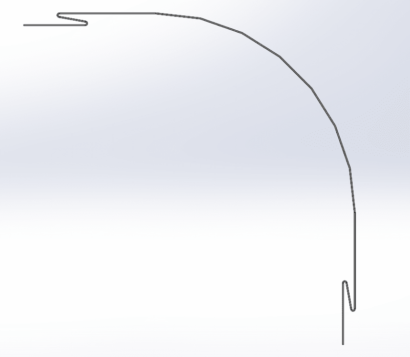
Here is where I am running into some issues; I would like to create a Part Profile for this trim so I can easily recreate it for other desired lengths. Is there a way to take the side profile that is shown above and have SolidWorks Auto-Generate lines so that I can create a new part and then create a Part Profile from it? Or is there a way to create a Part Profile right from the side view of the Sheet Metal part I created?
Just trying to figure out something more accurate than tracing as the numbers don't match when I try to recreate the side profile with my own sketch on top of the existing part.
Cheers,
LR
Back at y'all with another question that is probably more simple than I think... I'm currently working on a project to create some Aluminum trim and decided to use the Sheet Metal tool in SolidWorks as we use a Bending Machine here to get desired angles/hem's. A photo of the Side Profile that I designed can be seen below:
Here is where I am running into some issues; I would like to create a Part Profile for this trim so I can easily recreate it for other desired lengths. Is there a way to take the side profile that is shown above and have SolidWorks Auto-Generate lines so that I can create a new part and then create a Part Profile from it? Or is there a way to create a Part Profile right from the side view of the Sheet Metal part I created?
Just trying to figure out something more accurate than tracing as the numbers don't match when I try to recreate the side profile with my own sketch on top of the existing part.
Cheers,
LR