Continue to Site

Eng-Tips is the largest engineering community on the Internet

Intelligent Work Forums for Engineering Professionals

  • Congratulations GregLocock on being selected by the Eng-Tips community for having the most helpful posts in the forums last week. Way to Go!

Creating or editing free edges (cross sections of deformed/ undeformed beams)-Abaqus postprocessing 1

Status
Not open for further replies.

MaksatD

Industrial
Jul 31, 2013
5
Hi guys,
As most of those who post questions I am new to Abaqus. Trying to complete data creation after analysis but stuck here and cannot go further. I would like to compare (dimensional) free edges of deformed/ undeformed beam as in attached snapshot.

May you pl. advise if it is possible with Abaqus or if I have to export the geometry for another software or so?

Thanks in advance,
Cheers,
M.D.
 
 https://files.engineering.com/getfile.aspx?folder=ddc0ed4f-fb2a-4cf5-86bc-6045b7b8c82f&file=SmartSelect_20190520-033813_Chrome.jpg
Replies continue below

Recommended for you

In Abaqus you can create overlay plot of undeformed and deformed beam and set the view in such way to see the cross-section deformation like in the picture. However there will be no 2D axes to measure the value of deformation. But if you save the position of nodes on that free edge before and after the deformation (deformed coordinates can be found in Abaqus too) you can import the data to some special software like MatLab or SciLab and plot it easily.
 
Hello,

I have been trying to obtain coordinates of particular nodes set in deformed/ undeformed beams as you said. But not quite sure how to get them specifically without having to extract all the nodes of the model.

Could you pl. advise specifically how can this be achieved? In field output feature there are coord 1, 2 and 3...

Thanks in advance,
Maksat
 
Here's how to do it:
- create a set containing the nodes on that edge
- undeformed coordinates of these nodes can be determined using Query --> Node (choose previously created node set for this query)
- create a display group containing that node set
- select Query --> Probe Values, choose Probe:Nodes, then "Select a display group" and choose that node set again, you will get coordinates of its nodes (both deformed and undeformed)
- select "Write to file" to save these coordinates, delete output variable values and leave only coordinates
- now you can postprocess them in Excel or some data manipulation software

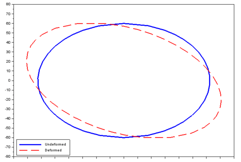
Here's an example - I analyzed torsion of elliptical bar in Abaqus, then followed the procedure described above and generated plot in SciLab. It required some effort due to the need to clear the data but here's what I got in the end:

plot_gwm7ff.png
 
Hello again,

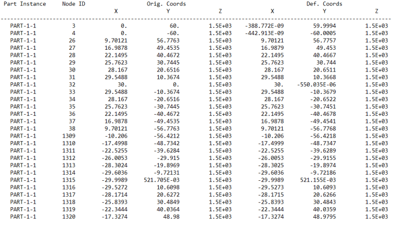
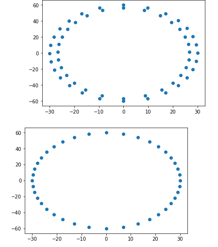
Thank you for your effort, while your response is very clear I believe I am having a technical issue, tried to plot the cross sections with python Jupyter notebook, I can do this for original coordinates but not sure if I get correct nodes for the deformed part. The report file I get has two sets of data points. Not sure which stands for original/ deformed coordinates because they give dubious results in my findings.

For instance, after creating a display group (under visualization module, by selecting nodes on the deformed shape), I perform Boolean operator to display only those selected nodes, and these sets of nodes (in the report file) are having different number of nodes:

1st_set_uxcnod.png


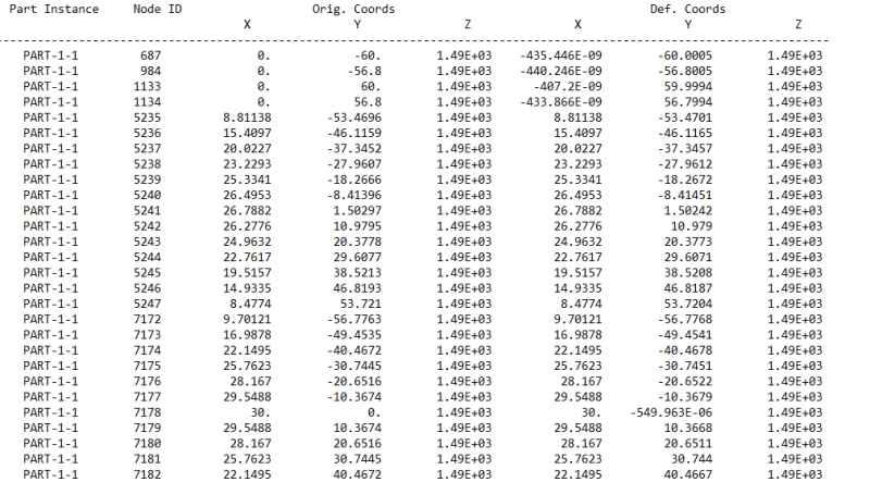
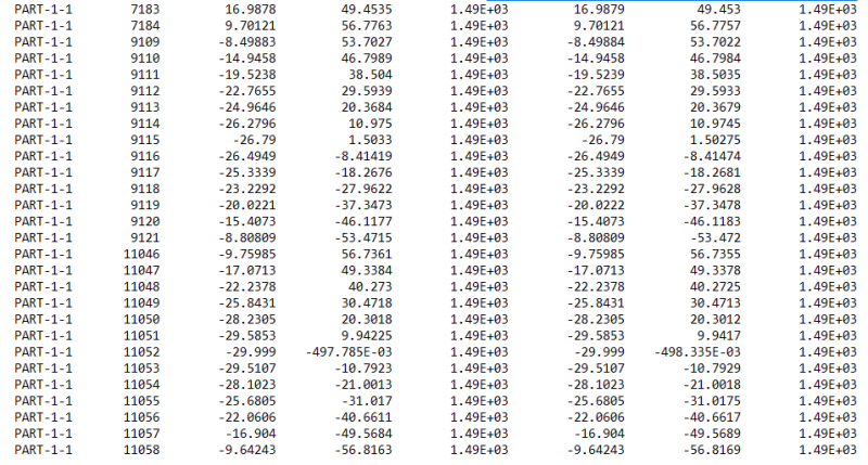
Second set of node coordinates which has different number of nodes (Which one stands for deformed nodes?):
2nd_set-1_zfvjhj.png

2nd_set-2_nzog7u.png


And here is the scatter plot I get:

plots_vbfijs.png


Thanks in advance,
M.D.
 
Those three columns (X,Y,Z) above which there’s a label „Orig. Coords” contain undeformed coordinates while columns with „Def. Coords” contain deformed coordinates. Make sure that the deformation of your cross-section is high enough to be visible when you plot it from these points (check it on the deformed shape contour plot in Abaqus with deformation scale set to 1). You may also increase the precision (number of decimal places) when you write this file from Probe values to see the differences between original and deformed coordinates.
 
Hello,

Deformation is highly visible, I select esp. those nodes in view cut to see the difference right away.
In my abaqus.rpt file I get both "orig cords". and "def. coords" same. (Always getting original shape).

Ecnounter following warning when click on replace in the DisplayGroup options to select nodes and highlight in viewport to avoid running for whole model:

"Warning: Display groups containing only nodes are not supported in contour plot mode. Select a different plot mode and activate node symbols and/or labels to see the selected nodes."

I have been doing all these opening .odb file and in visualization module.

Thanks,
Maksat
 
To avoid this error switch to Plot —> Undeformed Shape.

It may look like a high deformation but make sure that the scale of your deformed shape or contour plot is not higher than 1. You can check this in Options —> Common —> Basic __> Deformation Scale Factor. I think that this may be a reason due to the fact that the values of deformed coordinates are the same as those of undeformed coordinates, as you say.
 
Thank you.

I have not considered setting the deformation scale previously and now I regret.

Cheers,
M.D.
 
Status
Not open for further replies.

Part and Inventory Search

Sponsor