Rohan Ahrawal
Student
- Dec 8, 2024
- 2
I'm performing a creep analysis on a dogbone specimen made of SS-304. I am following this paper Correlation Analysis of Established Creep Failure Models through Computational Modelling for SS-304 Material.
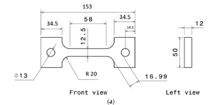
Following is the geometry:
In property module I've created the material, specifying Young's modulus (201000 MPa) and Poisson's ratio (0.31) on sheet "Elastic" and specifying Power Law Multiplier (6.18e-17), equation stress order (6.82) and time order (0) in sheet "Creep".
Then I create Visco step in Step module, specifying a time period of 6480000 sec (18000 Hr); in the sheet "Incrementation" I've chosen the max number of increment (10000), Initial increment size (1), minimum (1e-20) and max (360000), then I've chosen creep/swlling...tolerance (0.1).
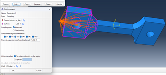
After that I've created a coupling constraint in Interaction module, then a reference point for the whole grip section with neck section of the specimen.
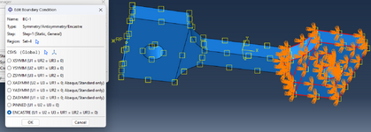
I've created a symmetry BC for the bottom section of grip and neck.
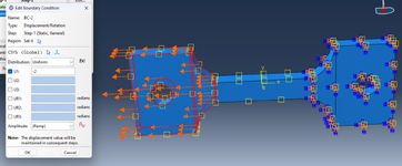
Then I've defined a load (displacement) of 2mm Magnitude. Also a thermal field is also defined of 720°C.
I've done the mesh, I’ve created and started the job, but I am getting wrong stress results but the creep results are somewhat In line. More over the creep curve trend also matched that of the literature, But not for stress results,
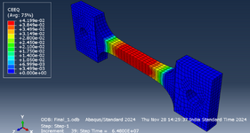
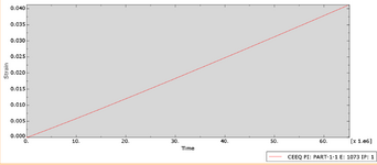
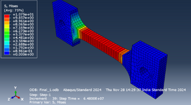
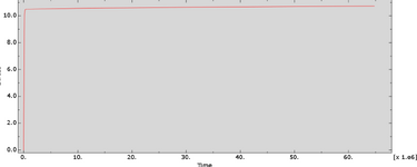
Any suggestion on how to fix the problem.
Following is the geometry:

In property module I've created the material, specifying Young's modulus (201000 MPa) and Poisson's ratio (0.31) on sheet "Elastic" and specifying Power Law Multiplier (6.18e-17), equation stress order (6.82) and time order (0) in sheet "Creep".
Then I create Visco step in Step module, specifying a time period of 6480000 sec (18000 Hr); in the sheet "Incrementation" I've chosen the max number of increment (10000), Initial increment size (1), minimum (1e-20) and max (360000), then I've chosen creep/swlling...tolerance (0.1).
After that I've created a coupling constraint in Interaction module, then a reference point for the whole grip section with neck section of the specimen.

I've created a symmetry BC for the bottom section of grip and neck.

Then I've defined a load (displacement) of 2mm Magnitude. Also a thermal field is also defined of 720°C.

I've done the mesh, I’ve created and started the job, but I am getting wrong stress results but the creep results are somewhat In line. More over the creep curve trend also matched that of the literature, But not for stress results,


Any suggestion on how to fix the problem.
Last edited:
